
Statics and Mechanics of Materials (5th Edition)
5th Edition
ISBN: 9780134382593
Author: Russell C. Hibbeler
Publisher: PEARSON
expand_more
expand_more
format_list_bulleted
Concept explainers
Videos
Textbook Question
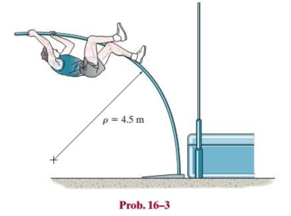
Chapter 16.2, Problem 3P
A picture is taken of a man performing a pole vault, and the minimum radius of curvature of the pole is estimated by measurement to be 4.5 m. If the pole is 40 mm in diameter and it is made of a glass-reinforced plastic for which Eg = 131 GPa, determine the maximum bending stress in the pole.
Expert Solution & Answer
Want to see the full answer?
Check out a sample textbook solution
Students have asked these similar questions
A long concrete footing rests on an earth founda-
tion for which the value of the foundation modulus is 5-6 MN/m2. The
footing has a cross-section 200 mm wide and 200 mm deep. The footing
supports a uniformly distributed load of 2 kN/m of length which ex-
tends over a 3 m length. Compute the value of the maximum bending
moment in the footing and the maximum bending stress. E = 14 GN/m2.
A leaf spring 75 cm long is required to carry a
central load of 8 kN. If the central deflection is not to exceed 2 cm and
bending stress no greater than 200 MPa, determine the thickness, width
and number of plates.
Also compute the radius to which plates should be curved. As-
sume width of plate to be 12 times its thickness and E = 200 GPa.
Calculate the internal shear forces and the value of
bending moments at points A, D (on member DB
and member AD), and B.
Origin
C
2 m
D
2.5 m
250 mm
125 mm
1.5 m
50 mm
( 25 kN /m
B
4m
- 2 m-
Chapter 16 Solutions
Statics and Mechanics of Materials (5th Edition)
Ch. 16.2 - In each ease, determine the internal bending...Ch. 16.2 - Prob. 1FPCh. 16.2 - Determine the slope and deflection of end A of the...Ch. 16.2 - Prob. 3FPCh. 16.2 - Prob. 4FPCh. 16.2 - Determine the maximum deflection of the simply...Ch. 16.2 - Prob. 6FPCh. 16.2 - An L2 steel strap having a thickness of 0.125 in....Ch. 16.2 - The L2 steel blade of the band saw wraps around...Ch. 16.2 - A picture is taken of a man performing a pole...
Ch. 16.2 - Determine the equation of the elastic curve for...Ch. 16.2 - Determine the deflection of end C of the...Ch. 16.2 - Prob. 6PCh. 16.2 - The A-36 steel beam has a depth of 10 in. and is...Ch. 16.2 - Prob. 8PCh. 16.2 - Determine the equations of the elastic curve for...Ch. 16.2 - Determine the equations of the elastic curve using...Ch. 16.2 - Determine the equations of the elastic curve using...Ch. 16.2 - Prob. 12PCh. 16.2 - Determine the maximum deflection of the beam and...Ch. 16.2 - The simply supported shaft has a moment of inertia...Ch. 16.2 - A torque wrench is used to tighten the nut on a...Ch. 16.2 - The pipe can be assumed roller supported at its...Ch. 16.2 - Determine the equations of the elastic curve for...Ch. 16.2 - The bar is supported by a roller constraint at B,...Ch. 16.2 - The bar is supported by a roller constraint at B,...Ch. 16.2 - Determine the equations of the elastic curve using...Ch. 16.2 - Prob. 21PCh. 16.2 - Determine the elastic curve for the cantilevered...Ch. 16.2 - Prob. 23PCh. 16.2 - Prob. 24PCh. 16.2 - The floor beam of the airplane is subjected to the...Ch. 16.2 - Determine the maximum deflection of the simply...Ch. 16.2 - The beam is made of a material having a specific...Ch. 16.2 - Determine the slope at end B and the maximum...Ch. 16.2 - Prob. 29PCh. 16.2 - Determine the equations of the elastic curve using...Ch. 16.3 - The shaft is supported at A by a journal bearing...Ch. 16.3 - The shaft supports the two pulley loads shown....Ch. 16.3 - Prob. 33PCh. 16.3 - Prob. 34PCh. 16.3 - The beam is subjected to the load shown. Determine...Ch. 16.3 - Prob. 36PCh. 16.3 - Determine the equation of the elastic curve and...Ch. 16.3 - Prob. 38PCh. 16.3 - Prob. 39PCh. 16.3 - Determine the slope at A and the deflection of end...Ch. 16.3 - Determine the maximum deflection in region AB of...Ch. 16.3 - Prob. 42PCh. 16.3 - Prob. 43PCh. 16.3 - Prob. 44PCh. 16.4 - The W10 15 cantilevered beam is made of A-36...Ch. 16.4 - The W10 15 cantilevered beam is made of A-36...Ch. 16.4 - The W14 43 simply supported beam is made of A992...Ch. 16.4 - The W14 43 simply supported beam is made of A992...Ch. 16.4 - The W14 43 simply supported beam is made of A-36...Ch. 16.4 - The W14 43 simply supported beam is made of A-36...Ch. 16.4 - The W8 48 cantilevered beam is made of A-36 steel...Ch. 16.4 - The beam supports the loading shown. Code...Ch. 16.4 - Prob. 53PCh. 16.4 - The W8 48 cantilevered beam is made of A-36 steel...Ch. 16.4 - Prob. 55PCh. 16.4 - Prob. 56PCh. 16.4 - Prob. 57PCh. 16.4 - The assembly consists of a cantilevered beam CB...Ch. 16.4 - Prob. 59PCh. 16.4 - Prob. 60PCh. 16.5 - Determine the reactions at the fixed support A and...Ch. 16.5 - Prob. 8FPCh. 16.5 - Determine the reactions at the fixed support A and...Ch. 16.5 - Prob. 10FPCh. 16.5 - Prob. 11FPCh. 16.5 - Prob. 12FPCh. 16.5 - Prob. 61PCh. 16.5 - Determine the reactions at the supports, then draw...Ch. 16.5 - Determine the reactions at the supports, then draw...Ch. 16.5 - Prob. 64PCh. 16.5 - The beam is used to support the 20-kip load....Ch. 16.5 - Prob. 66PCh. 16.5 - Determine the reactions at the supports A and B....Ch. 16.5 - Before the uniform distributed load is applied to...Ch. 16.5 - Prob. 69PCh. 16.5 - Prob. 70PCh. 16.5 - The beam is supported by the bolted supports at...Ch. 16.5 - Prob. 72PCh. 16.5 - Prob. 73PCh. 16 - Prob. 1RPCh. 16 - Draw the bending-moment diagram for the shaft and...Ch. 16 - Prob. 3RPCh. 16 - Determine the equations of the elastic curve for...Ch. 16 - Determine the maximum deflection between the...Ch. 16 - Prob. 6RPCh. 16 - The framework consists of two A-36 steel...Ch. 16 - Prob. 8RPCh. 16 - Using the method of superposition, determine the...
Knowledge Booster


Learn more about
Need a deep-dive on the concept behind this application? Look no further. Learn more about this topic, mechanical-engineering and related others by exploring similar questions and additional content below.Similar questions
- The internal loadings at a cross section through the 120-mm-diameter drive shaft of a turbine consist of an axial force of 12.5 kN, a bending moment of 1.2 kN - m, and a torsional moment of 2.25 kN m. (Eigure 1). Figure 1.2 kN-m 12.5 kN 1 of 1 2.25 kN-marrow_forwardA man with his tools having a total weight W = 1.012 kN, steps on the retractable ladder. The ladder is supported by cables and two arms. If each arm carries half of the weight, what is the internal bending moment in the arm at the indicated cross-section S? Take h = 540 mm, l1 = 365 mm, l2 = 286 mm, and l3 = 761 mm. Cables- Arms 1000 mim W/2arrow_forwardConsider an 8-m long simply supported T-beam with overhangs loaded as shown below. 200 mm w kN/m 50 mm 50 kN-m 50 kN-m 200 mm 2 m 4 m 2 m 50 mm 1. Determine the location of the neutral axis measured from the top of the beam and the moment of inertia (in mm4) of the section about its neutral axis. Draw the shear and bending moment diagrams. Annotate all relevant values and distances. Determine the magnitude of the maximum negative 2. moment. Determine the minimum allowable strength of the beam in tension and the minimum allowable strength of the beam in compression. 3. Determine the maximum allowable load, w (in kN/m), that can be applied pn the beam. 4. B.arrow_forward
- Determine the minimum allowable height (h) in mm of the beam shown in the figure if the bending stress is not to exceed 20 MPа. 5 kN 2.5 kN/m 80 mm A E D 1.0 m 1.0 m 2 marrow_forwardThe beam has a rectangular cross-section as shown in Fig.5. (1) Draw the shear-force and bending-moment diagrams for this beam. (2) Determine the largest load P that can be supported on its overhanging ends so that the bending stress does not exceed σmax = 10 MPa.arrow_forwardA strip of steel 3 mm thick and 35 mm wide is bent round a cylindrical drum 4 mm in diameter. Determine the maximum stress set up in the strip and the bending moment which has to be applied to bend the strip to this curvature (E = 200 GPa) A hollow short cast iron column has outside and inside diameters of 250 mm and 150 mm respectively. The column is subjected to an axial load applied at a distance of 60 mm from the center of the section. (a) Calculate the maximum safe load if the allowable stresses are 110 MPa compressive and 30 MPa tensile, calculate also the position of the NA.arrow_forward
- 25. A fiberglass pipe is lifted by a sling, as shown in the figure. The outer diameter of the pipe is 100 mm, its thickness is 6 mm, and its mass density is 1500 kg/m³. The length of the pipe is 10 m and the distance between lifting points is 4 m. Determine the maximum bending stress in the pipe due its own weight. Marut Tiwari Marut Tiwariarrow_forwardA gantry crane of weight W=100 Kg moves across a bridge with the length I=5 m. The front axle of the crane (which is nearer end A) carries 3/4W whereas the rear axle (nearer end B) carries 1/4 W. The distance of the axles is b = 1/20. Determine the maximum value of the bending moment and enter your answer in N-m units.. Remember to also show all your work (FBDs, calculation steps, etc on the handworked file) HINT: Determine the shear and bending moment equations along the beam. Assume only concentrated loads at the front and rear axles.arrow_forwardSITUATION 2: AH = 6 m cantilever retaining wall is subjected to a soil pressure linearly varying from zero at the top to 90 kPa at the bottom. As an additional support, it is anchored at depth y = 2 m. with maximum tension equal to 25 kN. Calculate: (a) Maximum positive bending moment per linear meter; (b) maximum negative bending moment per linear meter; (c) maximum shear force per linear meter. Soil surface 25 kN H Anchor 90 kPa Stemarrow_forward
- Determine the internal normal force and shear force, and the bending moment in the beam at points C and D. Assume the support at B is a roller. Point C is located just to the right of the 8-kip load. For your explanation section, complete a FBD of the other side of the beam from the version you did to solve the problem. 8 kip 40 kip · ft A to to D B- 8 ft 8 ft- -8 ftarrow_forwardA T-beam has the dimensions shown in Fig. If it is made of an elastic perfectly plastic material having a tensile and compressive yield stress of sY = 250 MPa, determine the plastic moment that can be resisted by the beam.arrow_forwardA gantry crane of weight W=100 Kg moves across a bridge with the length /=5 m. The front axle of the crane (which is nearer end A) carries 3/4W whereas the rear axle (nearer end B) carries 1/4 W. The distance of the axles is b = 1/20. Determine the maximum value of the bending moment and enter your answer in N-m units.. Remember to also show all your work (FBDs, calculation steps, etc on the handworked file) HINT: Determine the shear and bending moment equations along the beam. Assume only concentrated loads at the front and rear axles. So it’s wrong answer 1136 N can anyone how to solve for it different ?arrow_forward
arrow_back_ios
SEE MORE QUESTIONS
arrow_forward_ios
Recommended textbooks for you
 Elements Of ElectromagneticsMechanical EngineeringISBN:9780190698614Author:Sadiku, Matthew N. O.Publisher:Oxford University Press
 Mechanics of Materials (10th Edition)Mechanical EngineeringISBN:9780134319650Author:Russell C. HibbelerPublisher:PEARSON
 Thermodynamics: An Engineering ApproachMechanical EngineeringISBN:9781259822674Author:Yunus A. Cengel Dr., Michael A. BolesPublisher:McGraw-Hill Education
 Control Systems EngineeringMechanical EngineeringISBN:9781118170519Author:Norman S. NisePublisher:WILEY
 Mechanics of Materials (MindTap Course List)Mechanical EngineeringISBN:9781337093347Author:Barry J. Goodno, James M. GerePublisher:Cengage Learning
 Engineering Mechanics: StaticsMechanical EngineeringISBN:9781118807330Author:James L. Meriam, L. G. Kraige, J. N. BoltonPublisher:WILEY
Elements Of Electromagnetics
Mechanical Engineering
ISBN:9780190698614
Author:Sadiku, Matthew N. O.
Publisher:Oxford University Press
Mechanics of Materials (10th Edition)
Mechanical Engineering
ISBN:9780134319650
Author:Russell C. Hibbeler
Publisher:PEARSON
Thermodynamics: An Engineering Approach
Mechanical Engineering
ISBN:9781259822674
Author:Yunus A. Cengel Dr., Michael A. Boles
Publisher:McGraw-Hill Education
Control Systems Engineering
Mechanical Engineering
ISBN:9781118170519
Author:Norman S. Nise
Publisher:WILEY
Mechanics of Materials (MindTap Course List)
Mechanical Engineering
ISBN:9781337093347
Author:Barry J. Goodno, James M. Gere
Publisher:Cengage Learning
Engineering Mechanics: Statics
Mechanical Engineering
ISBN:9781118807330
Author:James L. Meriam, L. G. Kraige, J. N. Bolton
Publisher:WILEY
Everything About COMBINED LOADING in 10 Minutes! Mechanics of Materials; Author: Less Boring Lectures;https://www.youtube.com/watch?v=N-PlI900hSg;License: Standard youtube license