
Mechanics of Materials
11th Edition
ISBN: 9780137605460
Author: Russell C. Hibbeler
Publisher: Pearson Education (US)
expand_more
expand_more
format_list_bulleted
Videos
Textbook Question
Chapter 12.9, Problem 18FP
Determine the reaction at the roller support B if it settles 5mm. E = 200 GPa and I = 65.0 (10−6) m4.
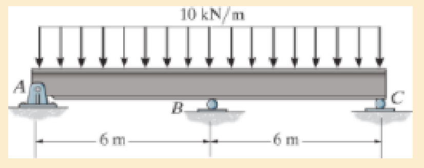
F12–18
Expert Solution & Answer

Trending nowThis is a popular solution!

Learn your wayIncludes step-by-step video

schedule05:10
Students have asked these similar questions
Determine the reactions
at the pin "A" and the
roller E", if (p= 500 N).
4000 N
30
B
3 m
C
An
4 m
4 m
A steel rod is bent to form a mounting
bracket. For each of the mounting brackets
and loading shown, determine the reactions
at A and B. Take L=200 mm, f2= 120 N , M=
13N.m, f1=70N
F2
150 mm
M
F1
30 mm
-225 mm
Determine the components of reaction at E. Take that P= 5.1
kN and w = 3.6 kN/m (Figure 1)
Figure
1 of 1
1.5 m
-1.5 m
Chapter 12 Solutions
Mechanics of Materials
Ch. 12.2 - Determine the slope and deflection of end A of the...Ch. 12.2 - Determine the slope and deflection of end A of the...Ch. 12.2 - Determine the slope of end A of the cantilevered...Ch. 12.2 - Determine the maximum deflection of the simply...Ch. 12.2 - Determine the maximum deflection of the simply...Ch. 12.2 - Determine the slope of the simply supported beam...Ch. 12.2 - An L2 steel strap having a thickness of 0.125 in....Ch. 12.2 - The L2 steel blade of the band saw wraps around...Ch. 12.2 - A picture is taken of a man performing a pole...Ch. 12.2 - A torque wrench is used to tighten the nut on a...
Ch. 12.2 - The pipe can be assumed roller supported at its...Ch. 12.2 - Determine the equations of the elastic curve for...Ch. 12.2 - Determine the equations of the elastic curve using...Ch. 12.2 - Determine the maximum deflection of the solid...Ch. 12.2 - Determine the equation of the elastic curve using...Ch. 12.2 - Determine the equations of the elastic curve using...Ch. 12.3 - The shaft supports the two pulley loads shown....Ch. 12.3 - Determine the equation of the elastic curve, the...Ch. 12.3 - Determine the equation of the elastic curve and...Ch. 12.3 - Determine the maximum deflection of the...Ch. 12.3 - Prob. 45PCh. 12.3 - Prob. 46PCh. 12.3 - Prob. 47PCh. 12.3 - Prob. 48PCh. 12.4 - Determine the slope and deflection of end A of the...Ch. 12.4 - Determine the slope and deflection of end A of the...Ch. 12.4 - Determine the slope and deflection of end A of the...Ch. 12.4 - Determine the slope and deflection at A of the...Ch. 12.4 - Prob. 11FPCh. 12.4 - Determine the maximum deflection of the simply...Ch. 12.4 - Determine the slope and deflection at C. El is...Ch. 12.4 - Prob. 54PCh. 12.4 - The composite simply supported steel shaft is...Ch. 12.4 - Determine the maximum deflection of the...Ch. 12.4 - Prob. 60PCh. 12.4 - Determine the slope at A and the maximum...Ch. 12.4 - Determine the displacement of the 20-mm-diameter...Ch. 12.4 - The two force components act on the tire of the...Ch. 12.4 - Determine the slope at B and deflection at C. El...Ch. 12.4 - Prob. 79PCh. 12.5 - The W10 15 cantilevered beam is made of A-36...Ch. 12.5 - The W14 43 simply supported beam is made of A992...Ch. 12.5 - The W14 43 simply supported beam is made of A992...Ch. 12.5 - The W14 43 simply supported beam is made of A-36...Ch. 12.7 - Determine the reactions at the supports A and B,...Ch. 12.7 - Determine the reactions at the supports A, B, and...Ch. 12.7 - Determine the reactions at the supports A and B,...Ch. 12.7 - The beam has a constant E1I1 and is supported by...Ch. 12.8 - Determine the reaction at the supports, then draw...Ch. 12.9 - Determine the reactions at the fixed support A and...Ch. 12.9 - Determine the reactions at the fixed support A and...Ch. 12.9 - Determine the reactions at the fixed support A and...Ch. 12.9 - Determine the reaction at the roller B. EI is...Ch. 12.9 - Determine the reaction at the roller B. EI is...Ch. 12.9 - Determine the reaction at the roller support B if...Ch. 12.9 - Determine the reactions at the journal bearing...Ch. 12.9 - Determine the reactions at the supports, then draw...Ch. 12.9 - Determine the reactions at the supports, then draw...Ch. 12.9 - The rim on the flywheel has a thickness t, width...Ch. 12.9 - Determine the moment developed in each corner....Ch. 12 - Determine the equation of the elastic curve. Use...Ch. 12 - Draw the bending-moment diagram for the shaft and...Ch. 12 - Determine the moment reactions at the supports A...Ch. 12 - Specify the slope at A and the maximum deflection....Ch. 12 - Determine the maximum deflection between the...Ch. 12 - Determine the slope at B and the deflection at C....Ch. 12 - Determine the reactions, then draw the shear and...Ch. 12 - El is constant.Ch. 12 - Using the method of superposition, determine the...
Additional Engineering Textbook Solutions
Find more solutions based on key concepts
What parts are included in the vehicle chassis?
Automotive Technology: Principles, Diagnosis, and Service (5th Edition)
State if these members are in tension or compression. Probs. 6-32
Engineering Mechanics: Statics
The data shown in the following graph was collected during testing of an electromagnetic mass driver. The energ...
Thinking Like an Engineer: An Active Learning Approach (3rd Edition)
Resolve the component force F1 into its x and y components, F1x and F1y . Resolve the component force F2 into i...
Engineering Mechanics: Statics & Dynamics (14th Edition)
For the manometer shown in Fig. 3.30, calculate (pA - Pb) Figure 3.30
Applied Fluid Mechanics (7th Edition)
Determine the angle for equilibrium and the force in cord AB.
INTERNATIONAL EDITION---Engineering Mechanics: Statics, 14th edition (SI unit)
Knowledge Booster


Learn more about
Need a deep-dive on the concept behind this application? Look no further. Learn more about this topic, mechanical-engineering and related others by exploring similar questions and additional content below.Similar questions
- Determine the magnitude of the horizontal component of the reaction at point A if F=287N , a=0.44m, b=1.97m, r=1.71m and d=28.1degrees. Round off only on the final answer expressed in 3 decimal places. Instead of units, indicate C if force is compressive or T if tensile.arrow_forwardA steel rod is bent to form a mounting bracket. For each of the mounting brackets and loading shown, determine the reactions at A and B. Take L=250 mm, f2= 68 N , M= * 14N.m , f1=50 N F2 B 150 mm 45 M F1 50 mm 225 mmarrow_forwardThe 50 kg block hangs from the cable which passes over the pulley at F. Neglecting the weights of the bars and the pulley, determine the magnitude of the pin reaction at D (in N). *Write your answer in two decimal places. C 2.5 m B F 2.5m R = 0.35m %3D W E 4 m - 4 m A.arrow_forward
- A steel rod is bent to form a mounting bracket. For each of the mounting brackets and loading shown, determine the reactions at A and B. Take L=250 mm, f2= 68 N , M= 14N.m, f1=50N F2 150 mm 45° M F1 0 mm 205 marrow_forward1.If d= 1.5 mm, and θ= 30∘, determine the normal reaction at the smooth support A if P = 900 N. Neglect the weight of the bar. NA=? 2.Determine the normal reaction at the smooth support B NB=? 3.Determine the required distance a for the placement of the roller. a=?arrow_forwardA steel rod is bent to form a mounting bracket. For each of the mounting brackets and loading shown, determine the reactions at A and B. Take L=230mm, F1=60N, F2=130 * N,M=14 N.m F2 L B 150 mm M F1 50 mm 225 mmarrow_forward
- Determine the components of reaction at the fixed support A. Neglect the thickness of the beam. 27.5 N 16.5 N 11 N 30° -1m1m- 1 m 5 m 4110 N 60° Aarrow_forwardA steel rod is bent to form a mounting bracket. For each of the mounting brackets and loading shown, determine the reactions at A and B. Take L=230mm, * F1=60N, F2-130 N,M=14 N.m F2 150 mmarrow_forwardThe weight W = 9 kN hangs from the cable which passes over the pulley at F. Neglecting the weights of the bars and the pulley, determine the magnitude of the hinge reaction at A in kN. 1.5 m B D 1.5 m R = 0.4 m A W E 2 m 2 marrow_forward
- 6:59 ull ? O 1 Moodle A moodle.ku.edu.kw Knowing that F = 4 kN. Determine the reactions %3D at the supports. F A 30° 6 m 2 m Ax = kN [→ +] %3D Ay = kN [↑ +] NB = kN [\ +] %3D Question 2 Not yet answerearrow_forwardThe member shown below is pin connected at A and rests against a smooth support at B. Determine the magnitude of the reaction at the support B. Set F= 70 N and M= 160 N.m B 30°/ M 0.8 m 1.4 m V 0.5 m F 306.7 N 122.5 N 373.9 N 322.5 N 258 Narrow_forwardA steel rod is bent to form a mounting bracket. For each of the mounting brackets and loading shown, determine the reactions at A and B. Take L=200 mm, f2= 120 N, M= 13N.m, f1=70Narrow_forward
arrow_back_ios
SEE MORE QUESTIONS
arrow_forward_ios
Recommended textbooks for you
 Elements Of ElectromagneticsMechanical EngineeringISBN:9780190698614Author:Sadiku, Matthew N. O.Publisher:Oxford University Press
 Mechanics of Materials (10th Edition)Mechanical EngineeringISBN:9780134319650Author:Russell C. HibbelerPublisher:PEARSON
 Thermodynamics: An Engineering ApproachMechanical EngineeringISBN:9781259822674Author:Yunus A. Cengel Dr., Michael A. BolesPublisher:McGraw-Hill Education
 Control Systems EngineeringMechanical EngineeringISBN:9781118170519Author:Norman S. NisePublisher:WILEY
 Mechanics of Materials (MindTap Course List)Mechanical EngineeringISBN:9781337093347Author:Barry J. Goodno, James M. GerePublisher:Cengage Learning
 Engineering Mechanics: StaticsMechanical EngineeringISBN:9781118807330Author:James L. Meriam, L. G. Kraige, J. N. BoltonPublisher:WILEY
Elements Of Electromagnetics
Mechanical Engineering
ISBN:9780190698614
Author:Sadiku, Matthew N. O.
Publisher:Oxford University Press
Mechanics of Materials (10th Edition)
Mechanical Engineering
ISBN:9780134319650
Author:Russell C. Hibbeler
Publisher:PEARSON
Thermodynamics: An Engineering Approach
Mechanical Engineering
ISBN:9781259822674
Author:Yunus A. Cengel Dr., Michael A. Boles
Publisher:McGraw-Hill Education
Control Systems Engineering
Mechanical Engineering
ISBN:9781118170519
Author:Norman S. Nise
Publisher:WILEY
Mechanics of Materials (MindTap Course List)
Mechanical Engineering
ISBN:9781337093347
Author:Barry J. Goodno, James M. Gere
Publisher:Cengage Learning
Engineering Mechanics: Statics
Mechanical Engineering
ISBN:9781118807330
Author:James L. Meriam, L. G. Kraige, J. N. Bolton
Publisher:WILEY
Dimensional Analysis - in physics; Author: Jennifer Cash;https://www.youtube.com/watch?v=c_ZUnEUlTbM;License: Standard youtube license