
Mechanics of Materials
11th Edition
ISBN: 9780137605460
Author: Russell C. Hibbeler
Publisher: Pearson Education (US)
expand_more
expand_more
format_list_bulleted
Videos
Textbook Question
Chapter 12.2, Problem 3P
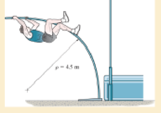
A picture is taken of a man performing a pole vault, and the minimum radius of curvature of the pole is estimated by measurement to be 4.5 m. If the pole is 40 mm in diameter and it is made of a glass-reinforced plastic for which Eg = 131 GPa, determine the maximum bending stress in the pole.
Prob. 12–3
Expert Solution & Answer

Learn your wayIncludes step-by-step video

schedule02:17
Students have asked these similar questions
The stepped bar has a thickness of 10 mm. Determine the maximum moment that can be applied to its ends if the allowable bending stress is sallow = 150 MPa.
The stepped bar has a thickness of 15 mm. Determine the maximum moment that can be applied to its ends if it is made
of a material having an allowable bending stress of 200 MPa.
45 mm
30 mm
3 mm
10 mm
6 mm
M
An L2 steel strap having a thickness of 0.125 in. and a width of 2 in. is bent into a circular arc of radius 600 in. Determine the maximum bending stress in the strap.
Chapter 12 Solutions
Mechanics of Materials
Ch. 12.2 - Determine the slope and deflection of end A of the...Ch. 12.2 - Determine the slope and deflection of end A of the...Ch. 12.2 - Determine the slope of end A of the cantilevered...Ch. 12.2 - Determine the maximum deflection of the simply...Ch. 12.2 - Determine the maximum deflection of the simply...Ch. 12.2 - Determine the slope of the simply supported beam...Ch. 12.2 - An L2 steel strap having a thickness of 0.125 in....Ch. 12.2 - The L2 steel blade of the band saw wraps around...Ch. 12.2 - A picture is taken of a man performing a pole...Ch. 12.2 - A torque wrench is used to tighten the nut on a...
Ch. 12.2 - The pipe can be assumed roller supported at its...Ch. 12.2 - Determine the equations of the elastic curve for...Ch. 12.2 - Determine the equations of the elastic curve using...Ch. 12.2 - Determine the maximum deflection of the solid...Ch. 12.2 - Determine the equation of the elastic curve using...Ch. 12.2 - Determine the equations of the elastic curve using...Ch. 12.3 - The shaft supports the two pulley loads shown....Ch. 12.3 - Determine the equation of the elastic curve, the...Ch. 12.3 - Determine the equation of the elastic curve and...Ch. 12.3 - Determine the maximum deflection of the...Ch. 12.3 - Prob. 45PCh. 12.3 - Prob. 46PCh. 12.3 - Prob. 47PCh. 12.3 - Prob. 48PCh. 12.4 - Determine the slope and deflection of end A of the...Ch. 12.4 - Determine the slope and deflection of end A of the...Ch. 12.4 - Determine the slope and deflection of end A of the...Ch. 12.4 - Determine the slope and deflection at A of the...Ch. 12.4 - Prob. 11FPCh. 12.4 - Determine the maximum deflection of the simply...Ch. 12.4 - Determine the slope and deflection at C. El is...Ch. 12.4 - Prob. 54PCh. 12.4 - The composite simply supported steel shaft is...Ch. 12.4 - Determine the maximum deflection of the...Ch. 12.4 - Prob. 60PCh. 12.4 - Determine the slope at A and the maximum...Ch. 12.4 - Determine the displacement of the 20-mm-diameter...Ch. 12.4 - The two force components act on the tire of the...Ch. 12.4 - Determine the slope at B and deflection at C. El...Ch. 12.4 - Prob. 79PCh. 12.5 - The W10 15 cantilevered beam is made of A-36...Ch. 12.5 - The W14 43 simply supported beam is made of A992...Ch. 12.5 - The W14 43 simply supported beam is made of A992...Ch. 12.5 - The W14 43 simply supported beam is made of A-36...Ch. 12.7 - Determine the reactions at the supports A and B,...Ch. 12.7 - Determine the reactions at the supports A, B, and...Ch. 12.7 - Determine the reactions at the supports A and B,...Ch. 12.7 - The beam has a constant E1I1 and is supported by...Ch. 12.8 - Determine the reaction at the supports, then draw...Ch. 12.9 - Determine the reactions at the fixed support A and...Ch. 12.9 - Determine the reactions at the fixed support A and...Ch. 12.9 - Determine the reactions at the fixed support A and...Ch. 12.9 - Determine the reaction at the roller B. EI is...Ch. 12.9 - Determine the reaction at the roller B. EI is...Ch. 12.9 - Determine the reaction at the roller support B if...Ch. 12.9 - Determine the reactions at the journal bearing...Ch. 12.9 - Determine the reactions at the supports, then draw...Ch. 12.9 - Determine the reactions at the supports, then draw...Ch. 12.9 - The rim on the flywheel has a thickness t, width...Ch. 12.9 - Determine the moment developed in each corner....Ch. 12 - Determine the equation of the elastic curve. Use...Ch. 12 - Draw the bending-moment diagram for the shaft and...Ch. 12 - Determine the moment reactions at the supports A...Ch. 12 - Specify the slope at A and the maximum deflection....Ch. 12 - Determine the maximum deflection between the...Ch. 12 - Determine the slope at B and the deflection at C....Ch. 12 - Determine the reactions, then draw the shear and...Ch. 12 - El is constant.Ch. 12 - Using the method of superposition, determine the...
Additional Engineering Textbook Solutions
Find more solutions based on key concepts
The moment of force about point O.
Engineering Mechanics: Statics & Dynamics (14th Edition)
Represent each force as a Cartesian vector and determine the magnitude and coordinate direction angles of the r...
INTERNATIONAL EDITION---Engineering Mechanics: Statics, 14th edition (SI unit)
7.12 A built-up steel member is composed of a
wide-flange section with a 12-in.-by- -in. plate welded to its to...
Applied Statics and Strength of Materials (6th Edition)
If it takes 1.5 s to travel from A to B, determine the velocity vA at which it was launched, the angle of relea...
Engineering Mechanics: Dynamics (14th Edition)
Determine the components of reaction at A and the tension in the cable needed to held the 800-lb cylinder in eq...
Engineering Mechanics: Statics
The data shown in the following graph was collected during testing of an electromagnetic mass driver. The energ...
Thinking Like an Engineer: An Active Learning Approach (3rd Edition)
Knowledge Booster


Learn more about
Need a deep-dive on the concept behind this application? Look no further. Learn more about this topic, mechanical-engineering and related others by exploring similar questions and additional content below.Similar questions
- The member has a circular cross section. If the allowable bending stress is sallow = 100 MPa, determine the maximum moment M that can be applied to the memberarrow_forwardDetermine the absolute maximum bending stress in the beam. Each segment has a rectangular cross section with a base of 4 in. and height of 12 in.arrow_forwardThe beam is made of Douglas fir having an allowable bending stress of sallow = 1.1 ksi and an allowable shear stress of tallow = 0.70 ksi. Determine the width b if the height h = 2b.arrow_forward
- The composite beam consists of a wood core and two plates of steel. If the allowable bending stress for the wood is (sallow)w = 20 MPa, and for the steel (sallow)st = 130 MPa, determine the maximum moment that can be applied to the beam. Ew = 11 GPa, Est = 200 GPa.arrow_forwardThe double-web girder is constructed from two plywood sheets that are secured to wood members at its top and bottom. The allowable bending stress for the wood is σallow = 8 ksi and the allowable shear stress is τallow = 3 ksi. The fasteners are spaced s = 6 in. and each fastener can support 400 lb in single shear. Determine the maximum load P that can be applied to the beam.arrow_forwardThe composite beam consists of a wood core and two plates of steel. If the allowable bending stress for the wood is (ơallow)w = 20 MPa, and for the steel (ơallow)st = 130 MPa, determine the maximum shear v that can be applied to the beam. Ew = 11 GPa, E = 200 GPa. 125 mm Given: (7allow),vood = 6.5 MPa E n = Ew 200(10°) 11(10°) = 18.182 1 (0.80227)(0.125) = 0.130578(10-³)m* 12 I = 20 mm- 75 mm Failure of wood : 20 mm Mc (om)max = I M(0.0625) 20(10°) M = 41.8 KN•M 0.130578(10 125mm Failure of steel : nMc (ơ1)max = I 18.182(M)(0.0625). 0.130578(10¬³) 130(10“) M = 14.9 kN •m (controls) A maximum moment that can be applied to the beam.arrow_forward
- A picture is taken of a man performing a pole vault, and the minimum radius of curvature of the pole is estimated by measurement to be 4.5 m. If the pole is 40 mm in diameter and it is made of a glass-reinforced plastic for which Eg = 131 GPa, determine the maximum bending stress in the pole.arrow_forwardThe beam has a rectangular cross section with a width of 8 in. and a height of 14 in. Determine the absolute maximum bending stress in the beam.arrow_forwardThe allowable bending stress for the bar is sallow = 200 MPa. Determine the maximum moment M that can be applied to the bar.arrow_forward
- The low strength concrete floor slab is integrated with a wide-flange A-36 steel beam using shear studs (not shown) to form the composite beam. If the allowable bending stress for the concrete is (σallow)con=10MPa(σallow)con=10MPa, and allowable bending stress for steel is (σallow)st=165MPa(σallow)st=165MPa, determine the maximum allowable internal moment MM that can be applied to the beam.arrow_forwardDetermine the internal normal force, shear force, and bending moment at point C in the beam. 10 kN 60 kN-m A- B- - 2 m- m--1 m- -2 m-arrow_forwardThe beam safely supports shear forces and bending moments of 2kN and 6.5 kN-m respectively. Based on this criterion, can it be safely subjected to the loads F = 1kN and C = 1.6 kN-m? Use the area methodarrow_forward
arrow_back_ios
SEE MORE QUESTIONS
arrow_forward_ios
Recommended textbooks for you
 Elements Of ElectromagneticsMechanical EngineeringISBN:9780190698614Author:Sadiku, Matthew N. O.Publisher:Oxford University Press
 Mechanics of Materials (10th Edition)Mechanical EngineeringISBN:9780134319650Author:Russell C. HibbelerPublisher:PEARSON
 Thermodynamics: An Engineering ApproachMechanical EngineeringISBN:9781259822674Author:Yunus A. Cengel Dr., Michael A. BolesPublisher:McGraw-Hill Education
 Control Systems EngineeringMechanical EngineeringISBN:9781118170519Author:Norman S. NisePublisher:WILEY
 Mechanics of Materials (MindTap Course List)Mechanical EngineeringISBN:9781337093347Author:Barry J. Goodno, James M. GerePublisher:Cengage Learning
 Engineering Mechanics: StaticsMechanical EngineeringISBN:9781118807330Author:James L. Meriam, L. G. Kraige, J. N. BoltonPublisher:WILEY
Elements Of Electromagnetics
Mechanical Engineering
ISBN:9780190698614
Author:Sadiku, Matthew N. O.
Publisher:Oxford University Press
Mechanics of Materials (10th Edition)
Mechanical Engineering
ISBN:9780134319650
Author:Russell C. Hibbeler
Publisher:PEARSON
Thermodynamics: An Engineering Approach
Mechanical Engineering
ISBN:9781259822674
Author:Yunus A. Cengel Dr., Michael A. Boles
Publisher:McGraw-Hill Education
Control Systems Engineering
Mechanical Engineering
ISBN:9781118170519
Author:Norman S. Nise
Publisher:WILEY
Mechanics of Materials (MindTap Course List)
Mechanical Engineering
ISBN:9781337093347
Author:Barry J. Goodno, James M. Gere
Publisher:Cengage Learning
Engineering Mechanics: Statics
Mechanical Engineering
ISBN:9781118807330
Author:James L. Meriam, L. G. Kraige, J. N. Bolton
Publisher:WILEY
Mechanics of Materials Lecture: Beam Design; Author: UWMC Engineering;https://www.youtube.com/watch?v=-wVs5pvQPm4;License: Standard Youtube License