
Mechanics of Materials
11th Edition
ISBN: 9780137605460
Author: Russell C. Hibbeler
Publisher: Pearson Education (US)
expand_more
expand_more
format_list_bulleted
Concept explainers
Videos
Textbook Question
Chapter 12.4, Problem 55P
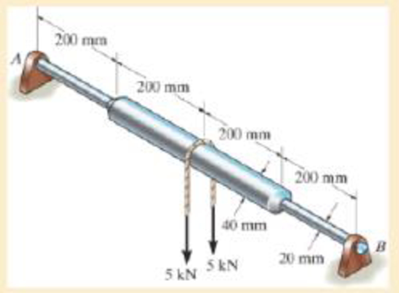
The composite simply supported steel shaft is subjected to a force of 10 kN at its center. Determine its maximum deflection. Est = 200 GPa.
Prob. 12–55
Expert Solution & Answer
Want to see the full answer?
Check out a sample textbook solution
Students have asked these similar questions
12-31. The shaft is made of steel and has a diameter of
15 mm. Determine its maximum deflection. The bearings
at A and B exert only vertical reactions on the shaft.
Est = 200 GPa.
-200 mm-
250 N
15 mm
-300 mm-
Prob. 12-31
80 N
-200 mm-
B
Determine the deflection of end C of the 100-mm-diameter solid circular shaft. Take E = 200 GPa.
F16-5. Determine the maximum deflection of the simply
supported beam. E = 200 GPa and / = 39.9(10) m.
40 kN m
10 kN-m
-6 m-
Chapter 12 Solutions
Mechanics of Materials
Ch. 12.2 - Determine the slope and deflection of end A of the...Ch. 12.2 - Determine the slope and deflection of end A of the...Ch. 12.2 - Determine the slope of end A of the cantilevered...Ch. 12.2 - Determine the maximum deflection of the simply...Ch. 12.2 - Determine the maximum deflection of the simply...Ch. 12.2 - Determine the slope of the simply supported beam...Ch. 12.2 - An L2 steel strap having a thickness of 0.125 in....Ch. 12.2 - The L2 steel blade of the band saw wraps around...Ch. 12.2 - A picture is taken of a man performing a pole...Ch. 12.2 - A torque wrench is used to tighten the nut on a...
Ch. 12.2 - The pipe can be assumed roller supported at its...Ch. 12.2 - Determine the equations of the elastic curve for...Ch. 12.2 - Determine the equations of the elastic curve using...Ch. 12.2 - Determine the maximum deflection of the solid...Ch. 12.2 - Determine the equation of the elastic curve using...Ch. 12.2 - Determine the equations of the elastic curve using...Ch. 12.3 - The shaft supports the two pulley loads shown....Ch. 12.3 - Determine the equation of the elastic curve, the...Ch. 12.3 - Determine the equation of the elastic curve and...Ch. 12.3 - Determine the maximum deflection of the...Ch. 12.3 - Prob. 45PCh. 12.3 - Prob. 46PCh. 12.3 - Prob. 47PCh. 12.3 - Prob. 48PCh. 12.4 - Determine the slope and deflection of end A of the...Ch. 12.4 - Determine the slope and deflection of end A of the...Ch. 12.4 - Determine the slope and deflection of end A of the...Ch. 12.4 - Determine the slope and deflection at A of the...Ch. 12.4 - Prob. 11FPCh. 12.4 - Determine the maximum deflection of the simply...Ch. 12.4 - Determine the slope and deflection at C. El is...Ch. 12.4 - Prob. 54PCh. 12.4 - The composite simply supported steel shaft is...Ch. 12.4 - Determine the maximum deflection of the...Ch. 12.4 - Prob. 60PCh. 12.4 - Determine the slope at A and the maximum...Ch. 12.4 - Determine the displacement of the 20-mm-diameter...Ch. 12.4 - The two force components act on the tire of the...Ch. 12.4 - Determine the slope at B and deflection at C. El...Ch. 12.4 - Prob. 79PCh. 12.5 - The W10 15 cantilevered beam is made of A-36...Ch. 12.5 - The W14 43 simply supported beam is made of A992...Ch. 12.5 - The W14 43 simply supported beam is made of A992...Ch. 12.5 - The W14 43 simply supported beam is made of A-36...Ch. 12.7 - Determine the reactions at the supports A and B,...Ch. 12.7 - Determine the reactions at the supports A, B, and...Ch. 12.7 - Determine the reactions at the supports A and B,...Ch. 12.7 - The beam has a constant E1I1 and is supported by...Ch. 12.8 - Determine the reaction at the supports, then draw...Ch. 12.9 - Determine the reactions at the fixed support A and...Ch. 12.9 - Determine the reactions at the fixed support A and...Ch. 12.9 - Determine the reactions at the fixed support A and...Ch. 12.9 - Determine the reaction at the roller B. EI is...Ch. 12.9 - Determine the reaction at the roller B. EI is...Ch. 12.9 - Determine the reaction at the roller support B if...Ch. 12.9 - Determine the reactions at the journal bearing...Ch. 12.9 - Determine the reactions at the supports, then draw...Ch. 12.9 - Determine the reactions at the supports, then draw...Ch. 12.9 - The rim on the flywheel has a thickness t, width...Ch. 12.9 - Determine the moment developed in each corner....Ch. 12 - Determine the equation of the elastic curve. Use...Ch. 12 - Draw the bending-moment diagram for the shaft and...Ch. 12 - Determine the moment reactions at the supports A...Ch. 12 - Specify the slope at A and the maximum deflection....Ch. 12 - Determine the maximum deflection between the...Ch. 12 - Determine the slope at B and the deflection at C....Ch. 12 - Determine the reactions, then draw the shear and...Ch. 12 - El is constant.Ch. 12 - Using the method of superposition, determine the...
Additional Engineering Textbook Solutions
Find more solutions based on key concepts
Assume the following vectors are already defined: V1=[302]V2=[214]V3=[5131]V4=[0.50.10.20.2] For each of the fo...
Thinking Like an Engineer: An Active Learning Approach (4th Edition)
Three rigid bodies, 2,3, and 4, are connected by four springs as shown in the figure. A horizontal force of 1,0...
Introduction To Finite Element Analysis And Design
A 20-lb force is applied to the control rod AB as shown. Knowing that the length of the rod is 9 in. and that t...
Statics and Mechanics of Materials
Compute the hydraulic radius for a circular drain pipe running half full if its inside diameter is 300 mm.
Applied Fluid Mechanics (7th Edition)
A pipe flowing light oil has a manometer attached, as shown in Fig, P1.52. What is the absolute pressure in pip...
Fundamentals Of Thermodynamics
23.23 A highly oxidized and uneven round bar is being turned on a lathe. Would you recommend a small or a large...
Manufacturing Engineering & Technology
Knowledge Booster


Learn more about
Need a deep-dive on the concept behind this application? Look no further. Learn more about this topic, mechanical-engineering and related others by exploring similar questions and additional content below.Similar questions
- F16-1. Determine the slape and deflection of end A of the cantilevered beam. E = 200 GPa and I = 65.0(10) mm. 30 kN-m -3m-arrow_forwardThe pipe assembly consists of three equal-sized pipes with flexibility stiffness EI and torsional stiffness GJ. Determine the vertical deflection at A.arrow_forwardAxial Deflection Prob 4. The assembly consists of two A-36 steel rods and a rigid bar BD. Each rod has a diameter of 0.75 in. If a force of 10 kip is applied to the bar, determine the angle of tilt of the bar. 2 11 B -1.25 ft- 0.75 ft 10 kip 3 ft 1 ftarrow_forward
- The framework consists of one cantilevered beam CB and a simply supported beam AB. If each beam is made of A-36 steel and has a moment of inertia about its principal axis of 1x = 65(106) mmª determine the deflection at the Point D at the centre of beam AB. 67 KN A C 4 m B D 2 m 2 marrow_forwardDetermine the internal moments at each joint using Slope-deflection equation method. El is constant. Set w = 10 kN/m. W RAVIGATE A YB —3m- 5.4 m - A C -—-—--—-—-4.5 m² 4arrow_forwardBar ABC has a rectangular cross section of 300 mm by 100 mm. The attached rod DB has a diameter of 20 mm. If both members are made of A-36 steel, determine the slope at A due to the loading. Consider only the effect of bending in ABC and axial force in DB.arrow_forward
- The rigid bar is supported by the pin-connected rod CB that has a cross-sectional area of 14 mm2 and is made from 6061-T6 aluminum. Determine the vertical deflection of the bar at D when the distributed load is applied.arrow_forward16-39. Determine the maximum deflection of the cantilevefed beam. Take E- 200 GPa and I-65.0(10) mm'. 15 kN 30 kN/m -1.5 m- -1.5 m-arrow_forward16-21. Determine the maximum deflection of the scolid circular shaft. The shaft is made of steel having E=200 GPa. It has a diameter of 100 mm. skN 6 kN-m 6 kN-m -15m. 15m.arrow_forward
- The rigid bar AD is supported by pin connection at point F and an elastic link AB. The link AB has the cross-sectional area 20 mm2 and made of red brass C83400 copper alloy. If P=200 N, determine the axial deflection of the link AB.arrow_forwardDetermine the deflection at x=2.5 m and x=8.arrow_forwardThe steel beam has a fixed support at A and a redundant hanger at B. The hanger rod has a cross sectional area of 3 in2. The member A-B has a moment of inertia I=300 in4. Determine: If the hanger were not attached at B, what would be the deflection at point B (E=29000 ksi)? With the hanger attached at B, determine the force carried in the rod BC. The stress carried in the rod BC. The reactions in the fixed support at A.arrow_forward
arrow_back_ios
SEE MORE QUESTIONS
arrow_forward_ios
Recommended textbooks for you
 Elements Of ElectromagneticsMechanical EngineeringISBN:9780190698614Author:Sadiku, Matthew N. O.Publisher:Oxford University Press
 Mechanics of Materials (10th Edition)Mechanical EngineeringISBN:9780134319650Author:Russell C. HibbelerPublisher:PEARSON
 Thermodynamics: An Engineering ApproachMechanical EngineeringISBN:9781259822674Author:Yunus A. Cengel Dr., Michael A. BolesPublisher:McGraw-Hill Education
 Control Systems EngineeringMechanical EngineeringISBN:9781118170519Author:Norman S. NisePublisher:WILEY
 Mechanics of Materials (MindTap Course List)Mechanical EngineeringISBN:9781337093347Author:Barry J. Goodno, James M. GerePublisher:Cengage Learning
 Engineering Mechanics: StaticsMechanical EngineeringISBN:9781118807330Author:James L. Meriam, L. G. Kraige, J. N. BoltonPublisher:WILEY
Elements Of Electromagnetics
Mechanical Engineering
ISBN:9780190698614
Author:Sadiku, Matthew N. O.
Publisher:Oxford University Press
Mechanics of Materials (10th Edition)
Mechanical Engineering
ISBN:9780134319650
Author:Russell C. Hibbeler
Publisher:PEARSON
Thermodynamics: An Engineering Approach
Mechanical Engineering
ISBN:9781259822674
Author:Yunus A. Cengel Dr., Michael A. Boles
Publisher:McGraw-Hill Education
Control Systems Engineering
Mechanical Engineering
ISBN:9781118170519
Author:Norman S. Nise
Publisher:WILEY
Mechanics of Materials (MindTap Course List)
Mechanical Engineering
ISBN:9781337093347
Author:Barry J. Goodno, James M. Gere
Publisher:Cengage Learning
Engineering Mechanics: Statics
Mechanical Engineering
ISBN:9781118807330
Author:James L. Meriam, L. G. Kraige, J. N. Bolton
Publisher:WILEY
Solids: Lesson 53 - Slope and Deflection of Beams Intro; Author: Jeff Hanson;https://www.youtube.com/watch?v=I7lTq68JRmY;License: Standard YouTube License, CC-BY