
Mechanics of Materials
11th Edition
ISBN: 9780137605460
Author: Russell C. Hibbeler
Publisher: Pearson Education (US)
expand_more
expand_more
format_list_bulleted
Concept explainers
Videos
Textbook Question
Chapter 12.4, Problem 72P
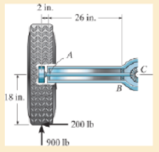
The two force components act on the tire of the automobile. The tire is fixed to the axle, which is supported by bearings at A and B. Determine the maximum deflection of the axle. Assume that the bearings resist only vertical loads. The thrust on the axle is resisted at C. The axle has a diameter of 1.25 in. and is made of A-36 steel. Neglect the effect of axial load on deflection.
Prob. 12–72
Expert Solution & Answer
Want to see the full answer?
Check out a sample textbook solution
Students have asked these similar questions
Axial Deflection
Prob 4. The assembly consists of two A-36 steel rods and
a rigid bar BD. Each rod has a diameter of 0.75 in. If a force
of 10 kip is applied to the bar, determine the angle of tilt of
the bar.
2 11
B
-1.25 ft-
0.75 ft
10 kip
3 ft
1 ft
Determine the maximum deflection of the axle. Assume that the bearings resist only vertical loads. The thrust on the axle is resisted at C. The axle has a diameter of 1.11 in. and is made of A-36 steel. Neglect the effect of
axial load on deflection.
Determine the deflection of end C of the 100-mm-diameter solid circular shaft. Take E = 200 GPa.
Chapter 12 Solutions
Mechanics of Materials
Ch. 12.2 - Determine the slope and deflection of end A of the...Ch. 12.2 - Determine the slope and deflection of end A of the...Ch. 12.2 - Determine the slope of end A of the cantilevered...Ch. 12.2 - Determine the maximum deflection of the simply...Ch. 12.2 - Determine the maximum deflection of the simply...Ch. 12.2 - Determine the slope of the simply supported beam...Ch. 12.2 - An L2 steel strap having a thickness of 0.125 in....Ch. 12.2 - The L2 steel blade of the band saw wraps around...Ch. 12.2 - A picture is taken of a man performing a pole...Ch. 12.2 - A torque wrench is used to tighten the nut on a...
Ch. 12.2 - The pipe can be assumed roller supported at its...Ch. 12.2 - Determine the equations of the elastic curve for...Ch. 12.2 - Determine the equations of the elastic curve using...Ch. 12.2 - Determine the maximum deflection of the solid...Ch. 12.2 - Determine the equation of the elastic curve using...Ch. 12.2 - Determine the equations of the elastic curve using...Ch. 12.3 - The shaft supports the two pulley loads shown....Ch. 12.3 - Determine the equation of the elastic curve, the...Ch. 12.3 - Determine the equation of the elastic curve and...Ch. 12.3 - Determine the maximum deflection of the...Ch. 12.3 - Prob. 45PCh. 12.3 - Prob. 46PCh. 12.3 - Prob. 47PCh. 12.3 - Prob. 48PCh. 12.4 - Determine the slope and deflection of end A of the...Ch. 12.4 - Determine the slope and deflection of end A of the...Ch. 12.4 - Determine the slope and deflection of end A of the...Ch. 12.4 - Determine the slope and deflection at A of the...Ch. 12.4 - Prob. 11FPCh. 12.4 - Determine the maximum deflection of the simply...Ch. 12.4 - Determine the slope and deflection at C. El is...Ch. 12.4 - Prob. 54PCh. 12.4 - The composite simply supported steel shaft is...Ch. 12.4 - Determine the maximum deflection of the...Ch. 12.4 - Prob. 60PCh. 12.4 - Determine the slope at A and the maximum...Ch. 12.4 - Determine the displacement of the 20-mm-diameter...Ch. 12.4 - The two force components act on the tire of the...Ch. 12.4 - Determine the slope at B and deflection at C. El...Ch. 12.4 - Prob. 79PCh. 12.5 - The W10 15 cantilevered beam is made of A-36...Ch. 12.5 - The W14 43 simply supported beam is made of A992...Ch. 12.5 - The W14 43 simply supported beam is made of A992...Ch. 12.5 - The W14 43 simply supported beam is made of A-36...Ch. 12.7 - Determine the reactions at the supports A and B,...Ch. 12.7 - Determine the reactions at the supports A, B, and...Ch. 12.7 - Determine the reactions at the supports A and B,...Ch. 12.7 - The beam has a constant E1I1 and is supported by...Ch. 12.8 - Determine the reaction at the supports, then draw...Ch. 12.9 - Determine the reactions at the fixed support A and...Ch. 12.9 - Determine the reactions at the fixed support A and...Ch. 12.9 - Determine the reactions at the fixed support A and...Ch. 12.9 - Determine the reaction at the roller B. EI is...Ch. 12.9 - Determine the reaction at the roller B. EI is...Ch. 12.9 - Determine the reaction at the roller support B if...Ch. 12.9 - Determine the reactions at the journal bearing...Ch. 12.9 - Determine the reactions at the supports, then draw...Ch. 12.9 - Determine the reactions at the supports, then draw...Ch. 12.9 - The rim on the flywheel has a thickness t, width...Ch. 12.9 - Determine the moment developed in each corner....Ch. 12 - Determine the equation of the elastic curve. Use...Ch. 12 - Draw the bending-moment diagram for the shaft and...Ch. 12 - Determine the moment reactions at the supports A...Ch. 12 - Specify the slope at A and the maximum deflection....Ch. 12 - Determine the maximum deflection between the...Ch. 12 - Determine the slope at B and the deflection at C....Ch. 12 - Determine the reactions, then draw the shear and...Ch. 12 - El is constant.Ch. 12 - Using the method of superposition, determine the...
Knowledge Booster


Learn more about
Need a deep-dive on the concept behind this application? Look no further. Learn more about this topic, mechanical-engineering and related others by exploring similar questions and additional content below.Similar questions
- 4. Determine the deflection of end C of the 100-mm-diameter solid circular shaft. Take E = 200 GPa. C B -2 m 1 m- 6 kNarrow_forward12-31. The shaft is made of steel and has a diameter of 15 mm. Determine its maximum deflection. The bearings at A and B exert only vertical reactions on the shaft. Est = 200 GPa. -200 mm- 250 N 15 mm -300 mm- Prob. 12-31 80 N -200 mm- Barrow_forwardDetermine the maximum deflection of the solid circular shaft. The shaft is made of steel having E = 200 GPa. It has a diameter of 100 mm.arrow_forward
- The steel beam has a fixed support at A and a redundant hanger at B. The hanger rod has a cross sectional area of 3 in2. The member A-B has a moment of inertia I=300 in4. Determine: If the hanger were not attached at B, what would be the deflection at point B (E=29000 ksi)? With the hanger attached at B, determine the force carried in the rod BC. The stress carried in the rod BC. The reactions in the fixed support at A.arrow_forwardThe pipe assembly consists of three equal-sized pipes with flexibility stiffness EI and torsional stiffness GJ. Determine the vertical deflection at A.arrow_forward16-51. Detemine the vertical deflection and slope at the cnd A of the bracket. Assume that the bracket is fixed supported at its base, and neglect the axial deformation of segment AB. El is constant. 4 kN/m 400 N -100 mm- 75 mmarrow_forward
- F16-5. Determine the maximum deflection of the simply supported beam. E = 200 GPa and / = 39.9(10) m. 40 kN m 10 kN-m -6 m-arrow_forwardBar ABC has a rectangular cross section of 300 mm by 100 mm. The attached rod DB has a diameter of 20 mm. If both members are made of A-36 steel, determine the slope at A due to the loading. Consider only the effect of bending in ABC and axial force in DB.arrow_forwardThe horizontal beam is assumed to be rigid while supporting the distributed load. Determine the angle of inclination of the beam after the load is applied. Each support consists of a wooden post with a diameter of 120 mm and an original length (unloaded) of 1.40 m- Consider E = 12 GPaarrow_forward
- The rigid arm AB is attached to the end of the solid circular steel rod BC. The rod is supported by bearings at B and a fixed support at C. The bearings at B prevent rod BC from translating up, down, left, or right, but the bearings do allow rod BC to rotate freely about the x axis at B. It is required that the vertical deflection of point A not exceed 0.25 in. when a load of P = 700 lb is applied at A. Determine the minimum diameter needed for rod BC. Use a = 18 in. and b = 45 in. The modulus of rigidity of the rod is G = 11×106 psi. A P Answer: dmin = i a B b in. Carrow_forward12-33. Determine the maximum deflection of the simply supported beam. E = 200 GPa and I = 65.0(106) mm4. -2 m- 30 kN 2 m 15 kN Prob. 12-33 -2 m- Barrow_forwardThe framework consists of one cantilevered beam CB and a simply supported beam AB. If each beam is made of A-36 steel and has a moment of inertia about its principal axis of 1x = 65(106) mmª determine the deflection at the Point D at the centre of beam AB. 67 KN A C 4 m B D 2 m 2 marrow_forward
arrow_back_ios
SEE MORE QUESTIONS
arrow_forward_ios
Recommended textbooks for you
 Elements Of ElectromagneticsMechanical EngineeringISBN:9780190698614Author:Sadiku, Matthew N. O.Publisher:Oxford University Press
 Mechanics of Materials (10th Edition)Mechanical EngineeringISBN:9780134319650Author:Russell C. HibbelerPublisher:PEARSON
 Thermodynamics: An Engineering ApproachMechanical EngineeringISBN:9781259822674Author:Yunus A. Cengel Dr., Michael A. BolesPublisher:McGraw-Hill Education
 Control Systems EngineeringMechanical EngineeringISBN:9781118170519Author:Norman S. NisePublisher:WILEY
 Mechanics of Materials (MindTap Course List)Mechanical EngineeringISBN:9781337093347Author:Barry J. Goodno, James M. GerePublisher:Cengage Learning
 Engineering Mechanics: StaticsMechanical EngineeringISBN:9781118807330Author:James L. Meriam, L. G. Kraige, J. N. BoltonPublisher:WILEY
Elements Of Electromagnetics
Mechanical Engineering
ISBN:9780190698614
Author:Sadiku, Matthew N. O.
Publisher:Oxford University Press
Mechanics of Materials (10th Edition)
Mechanical Engineering
ISBN:9780134319650
Author:Russell C. Hibbeler
Publisher:PEARSON
Thermodynamics: An Engineering Approach
Mechanical Engineering
ISBN:9781259822674
Author:Yunus A. Cengel Dr., Michael A. Boles
Publisher:McGraw-Hill Education
Control Systems Engineering
Mechanical Engineering
ISBN:9781118170519
Author:Norman S. Nise
Publisher:WILEY
Mechanics of Materials (MindTap Course List)
Mechanical Engineering
ISBN:9781337093347
Author:Barry J. Goodno, James M. Gere
Publisher:Cengage Learning
Engineering Mechanics: Statics
Mechanical Engineering
ISBN:9781118807330
Author:James L. Meriam, L. G. Kraige, J. N. Bolton
Publisher:WILEY
Solids: Lesson 53 - Slope and Deflection of Beams Intro; Author: Jeff Hanson;https://www.youtube.com/watch?v=I7lTq68JRmY;License: Standard YouTube License, CC-BY