
Mechanics of Materials
11th Edition
ISBN: 9780137605460
Author: Russell C. Hibbeler
Publisher: Pearson Education (US)
expand_more
expand_more
format_list_bulleted
Concept explainers
Videos
Textbook Question
Chapter 12.9, Problem 15FP
Determine the reactions at the fixed support A and the roller B. Support B settles 2 mm. E = 200 GPa, I = 65.0(10−6) m4.
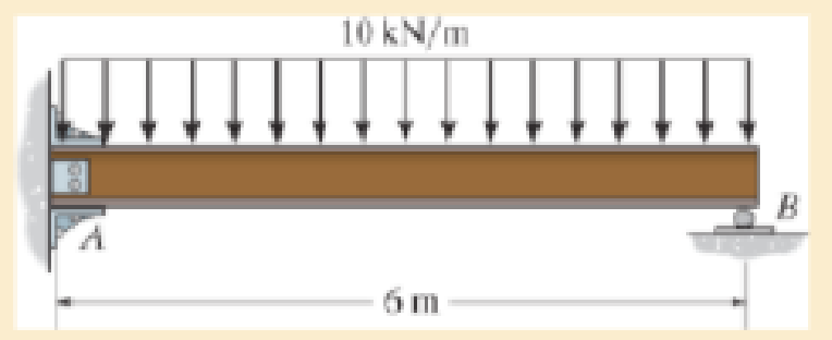
F12–15
Expert Solution & Answer
Want to see the full answer?
Check out a sample textbook solution
Students have asked these similar questions
Determine the reactions
at the pin "A" and the
roller E", if (p= 500 N).
4000 N
30
B
3 m
C
An
4 m
4 m
A steel rod is bent to form a mounting
bracket. For each of the mounting brackets
and loading shown, determine the reactions
at A and B. Take L=200 mm, f2= 120 N , M=
13N.m, f1=70N
F2
150 mm
M
F1
30 mm
-225 mm
Determine the components of reaction at E. Take that P= 5.1
kN and w = 3.6 kN/m (Figure 1)
Figure
1 of 1
1.5 m
-1.5 m
Chapter 12 Solutions
Mechanics of Materials
Ch. 12.2 - Determine the slope and deflection of end A of the...Ch. 12.2 - Determine the slope and deflection of end A of the...Ch. 12.2 - Determine the slope of end A of the cantilevered...Ch. 12.2 - Determine the maximum deflection of the simply...Ch. 12.2 - Determine the maximum deflection of the simply...Ch. 12.2 - Determine the slope of the simply supported beam...Ch. 12.2 - An L2 steel strap having a thickness of 0.125 in....Ch. 12.2 - The L2 steel blade of the band saw wraps around...Ch. 12.2 - A picture is taken of a man performing a pole...Ch. 12.2 - A torque wrench is used to tighten the nut on a...
Ch. 12.2 - The pipe can be assumed roller supported at its...Ch. 12.2 - Determine the equations of the elastic curve for...Ch. 12.2 - Determine the equations of the elastic curve using...Ch. 12.2 - Determine the maximum deflection of the solid...Ch. 12.2 - Determine the equation of the elastic curve using...Ch. 12.2 - Determine the equations of the elastic curve using...Ch. 12.3 - The shaft supports the two pulley loads shown....Ch. 12.3 - Determine the equation of the elastic curve, the...Ch. 12.3 - Determine the equation of the elastic curve and...Ch. 12.3 - Determine the maximum deflection of the...Ch. 12.3 - Prob. 45PCh. 12.3 - Prob. 46PCh. 12.3 - Prob. 47PCh. 12.3 - Prob. 48PCh. 12.4 - Determine the slope and deflection of end A of the...Ch. 12.4 - Determine the slope and deflection of end A of the...Ch. 12.4 - Determine the slope and deflection of end A of the...Ch. 12.4 - Determine the slope and deflection at A of the...Ch. 12.4 - Prob. 11FPCh. 12.4 - Determine the maximum deflection of the simply...Ch. 12.4 - Determine the slope and deflection at C. El is...Ch. 12.4 - Prob. 54PCh. 12.4 - The composite simply supported steel shaft is...Ch. 12.4 - Determine the maximum deflection of the...Ch. 12.4 - Prob. 60PCh. 12.4 - Determine the slope at A and the maximum...Ch. 12.4 - Determine the displacement of the 20-mm-diameter...Ch. 12.4 - The two force components act on the tire of the...Ch. 12.4 - Determine the slope at B and deflection at C. El...Ch. 12.4 - Prob. 79PCh. 12.5 - The W10 15 cantilevered beam is made of A-36...Ch. 12.5 - The W14 43 simply supported beam is made of A992...Ch. 12.5 - The W14 43 simply supported beam is made of A992...Ch. 12.5 - The W14 43 simply supported beam is made of A-36...Ch. 12.7 - Determine the reactions at the supports A and B,...Ch. 12.7 - Determine the reactions at the supports A, B, and...Ch. 12.7 - Determine the reactions at the supports A and B,...Ch. 12.7 - The beam has a constant E1I1 and is supported by...Ch. 12.8 - Determine the reaction at the supports, then draw...Ch. 12.9 - Determine the reactions at the fixed support A and...Ch. 12.9 - Determine the reactions at the fixed support A and...Ch. 12.9 - Determine the reactions at the fixed support A and...Ch. 12.9 - Determine the reaction at the roller B. EI is...Ch. 12.9 - Determine the reaction at the roller B. EI is...Ch. 12.9 - Determine the reaction at the roller support B if...Ch. 12.9 - Determine the reactions at the journal bearing...Ch. 12.9 - Determine the reactions at the supports, then draw...Ch. 12.9 - Determine the reactions at the supports, then draw...Ch. 12.9 - The rim on the flywheel has a thickness t, width...Ch. 12.9 - Determine the moment developed in each corner....Ch. 12 - Determine the equation of the elastic curve. Use...Ch. 12 - Draw the bending-moment diagram for the shaft and...Ch. 12 - Determine the moment reactions at the supports A...Ch. 12 - Specify the slope at A and the maximum deflection....Ch. 12 - Determine the maximum deflection between the...Ch. 12 - Determine the slope at B and the deflection at C....Ch. 12 - Determine the reactions, then draw the shear and...Ch. 12 - El is constant.Ch. 12 - Using the method of superposition, determine the...
Additional Engineering Textbook Solutions
Find more solutions based on key concepts
Repeat Problem 4-6 except solve by the vector loop method.
DESIGN OF MACHINERY
Select a mechanical component from Part 3 of this book (roller bearings, springs, etc.), go to the Internet, an...
Shigley's Mechanical Engineering Design (McGraw-Hill Series in Mechanical Engineering)
Assume the following vectors are already defined: V1=[302]V2=[214]V3=[5131]V4=[0.50.10.20.2] For each of the fo...
Thinking Like an Engineer: An Active Learning Approach (4th Edition)
19.8 Calculate the allowable tensile load for the connection shown. The plates are ASTM A36 steel and the weld ...
Applied Statics and Strength of Materials (6th Edition)
What types of coolant are used in vehicles?
Automotive Technology: Principles, Diagnosis, and Service (5th Edition)
Define or describe each type of fluid: (a) viscoelastic fluid (b) pseudoplastic fluid (c) dilatant fluid (d) Bi...
Fluid Mechanics: Fundamentals and Applications
Knowledge Booster


Learn more about
Need a deep-dive on the concept behind this application? Look no further. Learn more about this topic, mechanical-engineering and related others by exploring similar questions and additional content below.Similar questions
- 1.If d= 1.5 mm, and θ= 30∘, determine the normal reaction at the smooth support A if P = 900 N. Neglect the weight of the bar. NA=? 2.Determine the normal reaction at the smooth support B NB=? 3.Determine the required distance a for the placement of the roller. a=?arrow_forwardA steel rod is bent to form a mounting bracket. For each of the mounting brackets and loading shown, determine the reactions at A and B. Take L=230mm, * F1=60N, F2-130 N,M=14 N.m F2 150 mmarrow_forwardA steel rod is bent to form a mounting bracket. For each of the mounting brackets and loading shown, determine the reactions at A and B. Take L=250 mm, f2= 68 N , M= * 14N.m , f1=50 N F2 B 150 mm 45 M F1 50 mm 225 mmarrow_forward
- A steel rod is bent to form a mounting bracket. For each of the mounting brackets and loading shown, determine the reactions at A and B. Take L=200 mm, f2= 120 N, M= 13N.m, f1=70Narrow_forwardA steel rod is bent to form a mounting bracket. For each of the mounting brackets and loading shown, determine the reactions at A and B. Take L=230mm, F1=6ON, F2=130 N,M=14 N.m F2 L B 150 mm M Fl1 50 mm 225 mm-arrow_forwardA steel rod is bent to form a mounting bracket. For each of the mounting brackets and loading shown, determine the reactions at A and B. Take L=200 mm, f2= 120 N, M= 13N.m, f1=70 N 150 ma M FI ála äålal t.arrow_forward
- The 385-kg uniform l-beam supports the load shown. Determine the reactions at the supports. 4.8 m +3.2 m- 270 kg Answers: Ax = Ay= i N By = Narrow_forwardFind the reactions at D and B ..Take F1=200 N,F2=175 N, F3=150N, M=28 N.m, * F1 F2 85mm -75 mm M. 125 N 100 mm- 150 mm 50 mmarrow_forwardDetermine the reactions at the pin support A and the roller B. Take F = 6.5 kN and M = 3.5 kN.m F, 8 kN M 30 600 500 600 600 mm mm mm mm kN , Ay = kN and Ng kN.m %3D Ax =arrow_forward
- Determine the four support reactions. El is constant L=4m, q=5 kN/m A q L Barrow_forwardDetermine the external reactions at A and F for the roof truss loaded as shown (positive answers are to the right and up). The vertical loads represent the effect of the supported roofing materials, while the 430-N force represents a wind load. 430 N y 290 N A Answers: Ax= = Ay = Fy= 60° i B Mi 480 N 60° 30⁰ 520 N G 9.5 m 550 N 30° 30° 280 N N Z Z Z N N F xarrow_forwardDetermine the components of reaction at the fixed support A. Neglect the thickness of the beam. 27.5 N 16.5 N 11 N 30° -1m1m- 1 m 5 m 4110 N 60° Aarrow_forward
arrow_back_ios
SEE MORE QUESTIONS
arrow_forward_ios
Recommended textbooks for you
 Elements Of ElectromagneticsMechanical EngineeringISBN:9780190698614Author:Sadiku, Matthew N. O.Publisher:Oxford University Press
 Mechanics of Materials (10th Edition)Mechanical EngineeringISBN:9780134319650Author:Russell C. HibbelerPublisher:PEARSON
 Thermodynamics: An Engineering ApproachMechanical EngineeringISBN:9781259822674Author:Yunus A. Cengel Dr., Michael A. BolesPublisher:McGraw-Hill Education
 Control Systems EngineeringMechanical EngineeringISBN:9781118170519Author:Norman S. NisePublisher:WILEY
 Mechanics of Materials (MindTap Course List)Mechanical EngineeringISBN:9781337093347Author:Barry J. Goodno, James M. GerePublisher:Cengage Learning
 Engineering Mechanics: StaticsMechanical EngineeringISBN:9781118807330Author:James L. Meriam, L. G. Kraige, J. N. BoltonPublisher:WILEY
Elements Of Electromagnetics
Mechanical Engineering
ISBN:9780190698614
Author:Sadiku, Matthew N. O.
Publisher:Oxford University Press
Mechanics of Materials (10th Edition)
Mechanical Engineering
ISBN:9780134319650
Author:Russell C. Hibbeler
Publisher:PEARSON
Thermodynamics: An Engineering Approach
Mechanical Engineering
ISBN:9781259822674
Author:Yunus A. Cengel Dr., Michael A. Boles
Publisher:McGraw-Hill Education
Control Systems Engineering
Mechanical Engineering
ISBN:9781118170519
Author:Norman S. Nise
Publisher:WILEY
Mechanics of Materials (MindTap Course List)
Mechanical Engineering
ISBN:9781337093347
Author:Barry J. Goodno, James M. Gere
Publisher:Cengage Learning
Engineering Mechanics: Statics
Mechanical Engineering
ISBN:9781118807330
Author:James L. Meriam, L. G. Kraige, J. N. Bolton
Publisher:WILEY
EVERYTHING on Axial Loading Normal Stress in 10 MINUTES - Mechanics of Materials; Author: Less Boring Lectures;https://www.youtube.com/watch?v=jQ-fNqZWrNg;License: Standard YouTube License, CC-BY