
Mechanics of Materials
11th Edition
ISBN: 9780137605460
Author: Russell C. Hibbeler
Publisher: Pearson Education (US)
expand_more
expand_more
format_list_bulleted
Concept explainers
Videos
Textbook Question
Chapter 12.4, Problem 71P
Determine the displacement of the 20-mm-diameter A-36 steel shaft at D.
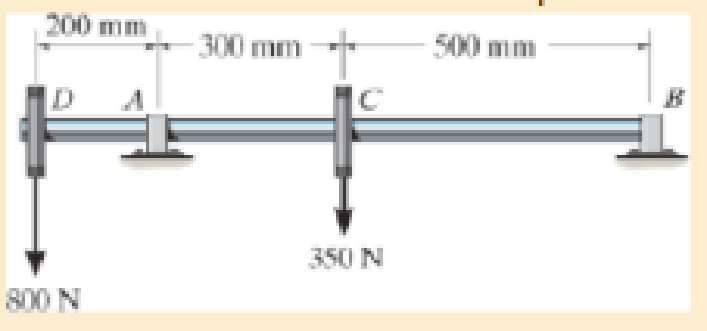
Prob. 12–71
Expert Solution & Answer
Want to see the full answer?
Check out a sample textbook solution
Students have asked these similar questions
Q7 (12 Marks)
For the system shown in Fig.3:
1- Draw the overall block diagram.
2- Determine the transfer function (Pc(s)/E(s)).
Orifice→
Ps
Actuating error signs)
Flapper
Pb+Pb.
Nozzle.
A
X+X+
Ri
A
I
R2
ㅍ
think
+y
Pc+PC
Figures 4: show a pneumatic controller. The pneumatic
relay has the characteristic
that pc=K pb
, where K>0. What kind of control action does this
controller produce?
a. Derive the mathematical model for the system
b. Derive the transfer function Pc(s)/E(s)
-Solve step by step
Orifice
F+Ph
R₁
Actuating error signal
Flapper
Nozzle.
x+x
F+Pe
think
The equation of the turning moment diagram for the three crank engine and the equation
of the moment required by a machine connected to this engine are given below:
Engine Torque
Machine Torque
T=10000-500 sin (40)
T=10000+2000 sin (20)
N.m
N.m
where
radians is the crank angle from inner dead center and the mean engine speed is
300 rpm. It is required to select a proper flywheel (find the moment of inertia of the flywheel
in kgm2) and then calculate the power of the engine if the total percentage fluctuation of
speed of the flywheel is ±1% of the mean speed. Calculate the angular acceleration of the
flywheel when angle is 45°.
Chapter 12 Solutions
Mechanics of Materials
Ch. 12.2 - Determine the slope and deflection of end A of the...Ch. 12.2 - Determine the slope and deflection of end A of the...Ch. 12.2 - Determine the slope of end A of the cantilevered...Ch. 12.2 - Determine the maximum deflection of the simply...Ch. 12.2 - Determine the maximum deflection of the simply...Ch. 12.2 - Determine the slope of the simply supported beam...Ch. 12.2 - An L2 steel strap having a thickness of 0.125 in....Ch. 12.2 - The L2 steel blade of the band saw wraps around...Ch. 12.2 - A picture is taken of a man performing a pole...Ch. 12.2 - A torque wrench is used to tighten the nut on a...
Ch. 12.2 - The pipe can be assumed roller supported at its...Ch. 12.2 - Determine the equations of the elastic curve for...Ch. 12.2 - Determine the equations of the elastic curve using...Ch. 12.2 - Determine the maximum deflection of the solid...Ch. 12.2 - Determine the equation of the elastic curve using...Ch. 12.2 - Determine the equations of the elastic curve using...Ch. 12.3 - The shaft supports the two pulley loads shown....Ch. 12.3 - Determine the equation of the elastic curve, the...Ch. 12.3 - Determine the equation of the elastic curve and...Ch. 12.3 - Determine the maximum deflection of the...Ch. 12.3 - Prob. 45PCh. 12.3 - Prob. 46PCh. 12.3 - Prob. 47PCh. 12.3 - Prob. 48PCh. 12.4 - Determine the slope and deflection of end A of the...Ch. 12.4 - Determine the slope and deflection of end A of the...Ch. 12.4 - Determine the slope and deflection of end A of the...Ch. 12.4 - Determine the slope and deflection at A of the...Ch. 12.4 - Prob. 11FPCh. 12.4 - Determine the maximum deflection of the simply...Ch. 12.4 - Determine the slope and deflection at C. El is...Ch. 12.4 - Prob. 54PCh. 12.4 - The composite simply supported steel shaft is...Ch. 12.4 - Determine the maximum deflection of the...Ch. 12.4 - Prob. 60PCh. 12.4 - Determine the slope at A and the maximum...Ch. 12.4 - Determine the displacement of the 20-mm-diameter...Ch. 12.4 - The two force components act on the tire of the...Ch. 12.4 - Determine the slope at B and deflection at C. El...Ch. 12.4 - Prob. 79PCh. 12.5 - The W10 15 cantilevered beam is made of A-36...Ch. 12.5 - The W14 43 simply supported beam is made of A992...Ch. 12.5 - The W14 43 simply supported beam is made of A992...Ch. 12.5 - The W14 43 simply supported beam is made of A-36...Ch. 12.7 - Determine the reactions at the supports A and B,...Ch. 12.7 - Determine the reactions at the supports A, B, and...Ch. 12.7 - Determine the reactions at the supports A and B,...Ch. 12.7 - The beam has a constant E1I1 and is supported by...Ch. 12.8 - Determine the reaction at the supports, then draw...Ch. 12.9 - Determine the reactions at the fixed support A and...Ch. 12.9 - Determine the reactions at the fixed support A and...Ch. 12.9 - Determine the reactions at the fixed support A and...Ch. 12.9 - Determine the reaction at the roller B. EI is...Ch. 12.9 - Determine the reaction at the roller B. EI is...Ch. 12.9 - Determine the reaction at the roller support B if...Ch. 12.9 - Determine the reactions at the journal bearing...Ch. 12.9 - Determine the reactions at the supports, then draw...Ch. 12.9 - Determine the reactions at the supports, then draw...Ch. 12.9 - The rim on the flywheel has a thickness t, width...Ch. 12.9 - Determine the moment developed in each corner....Ch. 12 - Determine the equation of the elastic curve. Use...Ch. 12 - Draw the bending-moment diagram for the shaft and...Ch. 12 - Determine the moment reactions at the supports A...Ch. 12 - Specify the slope at A and the maximum deflection....Ch. 12 - Determine the maximum deflection between the...Ch. 12 - Determine the slope at B and the deflection at C....Ch. 12 - Determine the reactions, then draw the shear and...Ch. 12 - El is constant.Ch. 12 - Using the method of superposition, determine the...
Knowledge Booster


Learn more about
Need a deep-dive on the concept behind this application? Look no further. Learn more about this topic, mechanical-engineering and related others by exploring similar questions and additional content below.Similar questions
- Design a cotter joint to support a axial load of 100kN . Carbon steel material selected whichhas Tensile stress = 100MPa Compressive stress =150MPa; Shear stress =60MPaarrow_forwardDesign a cotter joint to support a axial load of 100kN . Carbon steel material selected whichhas Tensile stress = 100MPa Compressive stress =150MPa; Shear stress =60MPaarrow_forwardI need all the derivations from Bohr's postulates in handwritten formarrow_forward
- 12. Figure Q12 shows a prospective design for a conveyor roller system, for transferring crates, one at a time. The system is made up of two parallel rectangular steel beams, built-in at one end and simply supported at the other, with closely spaced rollers mounted in-between, for the crate to pass over. a) Using Macaulay notation, carry out an analysis of the problem and calculate the deflection of the mid-length point of the beams when the crate is centrally located, midway between A and B. State any important assumptions used in your analysis. [20 marks] b) Comment briefly whether this would be the maximum deflection of the beams when the crate is centrally located. 2 m 8 m A Direction of travel Figure Q12 (side view, only one beam visible) Useful information I for each separate beam = 12 ×10 m² E for both beams = 210 GPa Weight of one crate = 800 N [5 marks] Barrow_forward11. A ring (side view shown in Figure Q11) has a circular solid cross-section of 5 mm diameter. The ring itself has a radius of R = 100 mm and a very narrow gap at point A, that allows the two free ends to be pulled apart by forces P, increasing the size of the gap. ○ P A Figure Q11 P a) Show that the total strain energy of the ring due to the applied forces is: U = 3πP²R³ 2EI [12 marks] b) Find the maximum bending stress produced if forces of P = 8 N are applied. [6 marks] c) What minimum force P would cause the material in the ring to yield and at which locations could this yielding begin to occur? Useful information E for the ring material = 75 GPa Oyield for the ring material = 190 MPa [7 marks]arrow_forwardQ2(15 Marks): From Fig. 2, Determine (a) mass equivalent in term x2, (b) stiffness equivalent in term x2, and (c) the natural frequency for the system in term x2. Note: (1) J Cylinder = mcr? J link (2) 2 3 Pulley, mass moment of inertia J Rigid link 1 (mass m₁), rotates with pulley. about O Cylinder, mass m Adherence to the symbols as in the question 152 153 xx(1) Fig. (2) m k₁ nimmunizmu Rigid link 2 (mass m₂)arrow_forward
- Q3-B (7 Marks): A mass (m) is suspended from a spring of stiffness 4000 N/m and is subjected to a harmonic force having an amplitude of 100 N and a frequency of 5 Hz. The amplitude of the forced motion of the mass is observed to be 20 mm. Find the value of mass (m).arrow_forwardFig. (2) Q3-A (8 Marks): An automobile is modeled as a single-degree-of-freedom system vibrating in the vertical direction. It is driven along a road whose elevation varies sinusoidally. The distance from peak to trough is 0.2 m and the distance along the road between the peaks is 35 m. If the natural frequency of the automobile is 2 Hz and the damping ratio of the shock absorbers is 0.15, determine the amplitude of vibration of the automobile at a speed of 60 km/hour 6.18arrow_forward2. Q4(15 Marks): The motor-pump system shown in Fig. 4. is modeled as a rigid bar of mass m=50 kg and mass moment of inertia Jo=100 kg-m. The foundation of the system can be replaced by two springs of stiffness k=500 N/m and k₂-200 N/m and L=1 m. Determine the natural frequencies of the system. Motor, Fig. (4) 1 6(1) Pump C.G. x(1) x₁(1) Base (a) Foundation (b) C.G. m, Jo x2(1)arrow_forward
- Q5(15 marks): Two equal pendulum free to rotate counterclockwise about the x-x axis are couple together by a rubber hose of torsional stiffness K lb.in/rad.as shown in Fig.5. determine the natural frequencies and mode shape for the normal modes of vibration. If L=19.3 in., W=3.86 lb, and k=20 lb.in/rad. Note: J=mL2 X (1) m 2 mc² 2 Xarrow_forwardUniversity of Babylon College of Engineering\Al-Musayab Automobile Engineering Department Final Examination/1st Attempt جامعة بابل Subject: I. C. Engines I Maximum Time: 3 Hours Class: 3rd Date: / / 2023 Answer 07 of the following questions (First Semester) 2022/2023 (1) Choose the correct answer for eight only from below 1- Indicator diagram shows for one complete revolution of crank Maximum mark: 50 Deg. a) variation of kinetic heat in the cylinder. b) variation of pressure head in the cylinder c) variation of kinetic and pressure heat in the cylinder. d) none of the above. 2- A carburetor is used to supply (a) petrol, air and lubricating oil (b) air and diesel (e) petrol and lubricating oil (d) petrol and air. 3- In a four stroke cycle petrol engine, the charge is compressed when a) inlet valve is closed. b) exit valve is closed. c) both inlet and exit valves are closed. d) both inlet and exit valves are open. (8 deg.) 4- For an engine operating on air standard Otto cycle, the…arrow_forward(6) Determine the sizes of fuel orifice to give a 13.5 air fuel ratio, if the venture throat has 3 cm diameter and the pressure drop in the venture is 6.5 cm Hg. The air temperature and pressure at carburetor entrance are 1 bar and 27 °C respectively. The fuel orifice is at the same level as that of the float chamber. Take density of gasoline as (7 deg.) 740 kg/m³ and discharge coefficient as unity. Assume atmospheric pressure to be 76 cm of Hg. (7) A four-cylinder, four-stroke internal combustion engine has a bore of 87 mm. and a stroke of 77 mm. The clearance volume is 17% of the stroke volume and the engine with speed of 2700 rpm. The processes within each cylinder are modeled as an Otto cycle with a pressure of 1 atm and a temperature of 17 °C at the beginning (7 deg.) of compression. The maximum temperature in the cycle is 2717 °C (a) Draw the P-v diagram; label Pressures, Temperatures, Qin, and Qual (b) Calculate the mass of air at the beginning of the cycle (c) Calculate the…arrow_forward
arrow_back_ios
SEE MORE QUESTIONS
arrow_forward_ios
Recommended textbooks for you
 International Edition---engineering Mechanics: St...Mechanical EngineeringISBN:9781305501607Author:Andrew Pytel And Jaan KiusalaasPublisher:CENGAGE L
International Edition---engineering Mechanics: St...
Mechanical Engineering
ISBN:9781305501607
Author:Andrew Pytel And Jaan Kiusalaas
Publisher:CENGAGE L
Solids: Lesson 53 - Slope and Deflection of Beams Intro; Author: Jeff Hanson;https://www.youtube.com/watch?v=I7lTq68JRmY;License: Standard YouTube License, CC-BY