
Mechanics of Materials
11th Edition
ISBN: 9780137605460
Author: Russell C. Hibbeler
Publisher: Pearson Education (US)
expand_more
expand_more
format_list_bulleted
Concept explainers
Videos
Textbook Question
Chapter 12.2, Problem 4FP
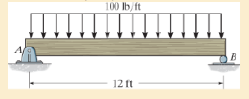
Determine the maximum deflection of the simply supported beam. The beam is made of wood having a modulus of elasticity of Ew = 1.5(103) ksi and a rectangular cross section of width b = 3 in. and height h = 6 in.
Expert Solution & Answer

Learn your wayIncludes step-by-step video

schedule13:57
Students have asked these similar questions
Determine the maximum deflection of the cantilevered beam. The beam is made of material having an E=200GPaE=200GPa and I=63(106)mm6I=63(106)mm4 . (Figure 1)
note the image is wrong, must be I=63(106)mm^4
For the beam loaded as shown, determine the deflection 6 ft from the wall. Use
E = 1.5 x 10⁶ psi and I = 40 in.*
80 lb/ft
B
8 ft
Use the conjugate-beam method and determine the slope just to the left and just to the right of the pin at B.
Also, determine the deflection at D. Assume the beam is fixed supported at A, and that C is a roller. Take
M = 20 kN m, L = 7 m and EI = 10000 KNM².
M
A
В
C
D'
L
Part 1)
The magnitude of slope just to the left of the pin at B, O BL = 2
10 3 rad
Your last answer was interpreted as follows: 2
Part 2)
The magnitude of slope just to the right of the pin at B, 0 BR =
1
10 3 rad
Your last answer was interpreted as follows: 1
Part 3)
The magnitude of displacement at D, Ap= |1
mm
Your last answer was interpreted as follows:1
Chapter 12 Solutions
Mechanics of Materials
Ch. 12.2 - Determine the slope and deflection of end A of the...Ch. 12.2 - Determine the slope and deflection of end A of the...Ch. 12.2 - Determine the slope of end A of the cantilevered...Ch. 12.2 - Determine the maximum deflection of the simply...Ch. 12.2 - Determine the maximum deflection of the simply...Ch. 12.2 - Determine the slope of the simply supported beam...Ch. 12.2 - An L2 steel strap having a thickness of 0.125 in....Ch. 12.2 - The L2 steel blade of the band saw wraps around...Ch. 12.2 - A picture is taken of a man performing a pole...Ch. 12.2 - A torque wrench is used to tighten the nut on a...
Ch. 12.2 - The pipe can be assumed roller supported at its...Ch. 12.2 - Determine the equations of the elastic curve for...Ch. 12.2 - Determine the equations of the elastic curve using...Ch. 12.2 - Determine the maximum deflection of the solid...Ch. 12.2 - Determine the equation of the elastic curve using...Ch. 12.2 - Determine the equations of the elastic curve using...Ch. 12.3 - The shaft supports the two pulley loads shown....Ch. 12.3 - Determine the equation of the elastic curve, the...Ch. 12.3 - Determine the equation of the elastic curve and...Ch. 12.3 - Determine the maximum deflection of the...Ch. 12.3 - Prob. 45PCh. 12.3 - Prob. 46PCh. 12.3 - Prob. 47PCh. 12.3 - Prob. 48PCh. 12.4 - Determine the slope and deflection of end A of the...Ch. 12.4 - Determine the slope and deflection of end A of the...Ch. 12.4 - Determine the slope and deflection of end A of the...Ch. 12.4 - Determine the slope and deflection at A of the...Ch. 12.4 - Prob. 11FPCh. 12.4 - Determine the maximum deflection of the simply...Ch. 12.4 - Determine the slope and deflection at C. El is...Ch. 12.4 - Prob. 54PCh. 12.4 - The composite simply supported steel shaft is...Ch. 12.4 - Determine the maximum deflection of the...Ch. 12.4 - Prob. 60PCh. 12.4 - Determine the slope at A and the maximum...Ch. 12.4 - Determine the displacement of the 20-mm-diameter...Ch. 12.4 - The two force components act on the tire of the...Ch. 12.4 - Determine the slope at B and deflection at C. El...Ch. 12.4 - Prob. 79PCh. 12.5 - The W10 15 cantilevered beam is made of A-36...Ch. 12.5 - The W14 43 simply supported beam is made of A992...Ch. 12.5 - The W14 43 simply supported beam is made of A992...Ch. 12.5 - The W14 43 simply supported beam is made of A-36...Ch. 12.7 - Determine the reactions at the supports A and B,...Ch. 12.7 - Determine the reactions at the supports A, B, and...Ch. 12.7 - Determine the reactions at the supports A and B,...Ch. 12.7 - The beam has a constant E1I1 and is supported by...Ch. 12.8 - Determine the reaction at the supports, then draw...Ch. 12.9 - Determine the reactions at the fixed support A and...Ch. 12.9 - Determine the reactions at the fixed support A and...Ch. 12.9 - Determine the reactions at the fixed support A and...Ch. 12.9 - Determine the reaction at the roller B. EI is...Ch. 12.9 - Determine the reaction at the roller B. EI is...Ch. 12.9 - Determine the reaction at the roller support B if...Ch. 12.9 - Determine the reactions at the journal bearing...Ch. 12.9 - Determine the reactions at the supports, then draw...Ch. 12.9 - Determine the reactions at the supports, then draw...Ch. 12.9 - The rim on the flywheel has a thickness t, width...Ch. 12.9 - Determine the moment developed in each corner....Ch. 12 - Determine the equation of the elastic curve. Use...Ch. 12 - Draw the bending-moment diagram for the shaft and...Ch. 12 - Determine the moment reactions at the supports A...Ch. 12 - Specify the slope at A and the maximum deflection....Ch. 12 - Determine the maximum deflection between the...Ch. 12 - Determine the slope at B and the deflection at C....Ch. 12 - Determine the reactions, then draw the shear and...Ch. 12 - El is constant.Ch. 12 - Using the method of superposition, determine the...
Additional Engineering Textbook Solutions
Find more solutions based on key concepts
Figure 3.24 shows a closed container holding water and oil. Air at 34 kPa below atmosperic pressure is above th...
Applied Fluid Mechanics (7th Edition)
The magnitude of vector force F (F) and its direction θ.
Engineering Mechanics: Statics & Dynamics (14th Edition)
Determine the horizontal equilibrium force P that must be applied to the handle and the x, y, z components of r...
Engineering Mechanics: Statics
What parts are included in the vehicle chassis?
Automotive Technology: Principles, Diagnosis, And Service (6th Edition) (halderman Automotive Series)
Comprehension Check 7-1
Express the following values using an appropriate Sl prefix such that there are only on...
Thinking Like an Engineer: An Active Learning Approach (3rd Edition)
9.57 The steel piston rod to the master cylinder has a diameter of in. Determine the stress in the piston rod w...
Applied Statics and Strength of Materials (6th Edition)
Knowledge Booster


Learn more about
Need a deep-dive on the concept behind this application? Look no further. Learn more about this topic, mechanical-engineering and related others by exploring similar questions and additional content below.Similar questions
- 2. Using the conjugate beam method, determine the maximum deflection of the beam. Use E = 10,000 ksi and I = 500 in4. 30 k A B -14 ft- -7 ft-arrow_forwardDetermine the deflection at point B given the cross-section of the beam and assuming E = 200 GPa. 200 mm A 20 mm 8 kN 4kN/m A 200 mm C 30 mm 1 m 1 m 2 m 2 m 20 mmarrow_forwardDetermine the maximum deflection of the simply supported beam. The beam is made of wood having a modulus of elasticity of Ew = 1.5(103) ksi and a rectangular cross section of width b = 3 in. and height h = 6 in.arrow_forward
- A simply supported beam is subjected to a triangularly distributed load of Q = 6.0 kN/m over segment length L = 2.8 m. Determine the maximum slope and deflection of the beam. Assume El is constant. Q kN/m L Larrow_forward1. By using Three Moment Equation, determine the deflection at the midspan of the beam shown. 30 kN/m 5 m- El= constant E = 200 GPa 1=1460x10 mm¹ B -2m- сarrow_forwardDetermine the value of the slope and deflection of the beam at points B and C. E and I are constant over the beam length. (Set a = 4m, w = 5kN/m, E = 200 GPa, I = 114 x 106 mm4)arrow_forward
- Using Moment-Area Method, determine the slope at A and B and the deflection at point B of the loaded beam shown. Use E = 150 GPa and I = 110x106 mm4. (Please show moment diagrams by parts)arrow_forwardA simply supported beam of dimension 11.5 m x 45 mm x 75 mm. It carries a uniformly distributed load of 450 kN/m for entire span. Determine (a) Maximum stress due to bending and (b) Young's modulus of the material used for the beam, if it deflects 125 mm maximum at the mid of the span. Also find the maximum slope in the beam. Moment of inertia of the cross section of the beam in m4 = Young's modulus of the beam material in MPa is = Maximum bending stress due to bending in MPa is = The slope at the supports of beam in radians is =arrow_forwardA simply supported beam of dimension 12.5 m x 35 mm x 70 mm. It carries a uniformly distributed load of 450 kN/m for entire span. Determine (a) Maximum stress due to bending and (b) Young’s modulus of the material used for the beam, if it deflects 150 mm maximum at the mid of the span. Also find the maximum slope in the beam. Moment of inertia of the cross section of the beam in m4 = oung's modulus of the beam material in MPa is = Maximum bending stress due to bending in MPa is = The slope at the supports of beam in radians is =arrow_forward
- Determine the maximum deflection in region AB of the overhang beam. Take E = 29(103) ksi and I = 204 in4.arrow_forwardDetermine the slope and deflection at point B of the beam shown below by the moment- area method. 90 kN A B. 5 m El = constant E = 200 GPa I = 800 (106) mm4arrow_forward5. The rigid beam rests on two short posts AC and BD as shown. Post AC is made from steel with E-200 GPa and BD from aluminum with E-70 GPa. The diameters of posts AC and 80 are 25 mm and 40 mm, respectively. Determine the vertical displacement of point on AB 100 KN 400mm D 6. The timber beam has a cross-sectional area of 2000 mm and its modulus of elasticity is 12 GP Axial loads are applied at points B, C, and D as shown. Calculate the total change in length of the beam. Answer: 2.33 mm 40 KN 35 KN 20 KN 3.20 m 1.60m 3.20 marrow_forward
arrow_back_ios
SEE MORE QUESTIONS
arrow_forward_ios
Recommended textbooks for you
 Elements Of ElectromagneticsMechanical EngineeringISBN:9780190698614Author:Sadiku, Matthew N. O.Publisher:Oxford University Press
 Mechanics of Materials (10th Edition)Mechanical EngineeringISBN:9780134319650Author:Russell C. HibbelerPublisher:PEARSON
 Thermodynamics: An Engineering ApproachMechanical EngineeringISBN:9781259822674Author:Yunus A. Cengel Dr., Michael A. BolesPublisher:McGraw-Hill Education
 Control Systems EngineeringMechanical EngineeringISBN:9781118170519Author:Norman S. NisePublisher:WILEY
 Mechanics of Materials (MindTap Course List)Mechanical EngineeringISBN:9781337093347Author:Barry J. Goodno, James M. GerePublisher:Cengage Learning
 Engineering Mechanics: StaticsMechanical EngineeringISBN:9781118807330Author:James L. Meriam, L. G. Kraige, J. N. BoltonPublisher:WILEY
Elements Of Electromagnetics
Mechanical Engineering
ISBN:9780190698614
Author:Sadiku, Matthew N. O.
Publisher:Oxford University Press
Mechanics of Materials (10th Edition)
Mechanical Engineering
ISBN:9780134319650
Author:Russell C. Hibbeler
Publisher:PEARSON
Thermodynamics: An Engineering Approach
Mechanical Engineering
ISBN:9781259822674
Author:Yunus A. Cengel Dr., Michael A. Boles
Publisher:McGraw-Hill Education
Control Systems Engineering
Mechanical Engineering
ISBN:9781118170519
Author:Norman S. Nise
Publisher:WILEY
Mechanics of Materials (MindTap Course List)
Mechanical Engineering
ISBN:9781337093347
Author:Barry J. Goodno, James M. Gere
Publisher:Cengage Learning
Engineering Mechanics: Statics
Mechanical Engineering
ISBN:9781118807330
Author:James L. Meriam, L. G. Kraige, J. N. Bolton
Publisher:WILEY
Solids: Lesson 53 - Slope and Deflection of Beams Intro; Author: Jeff Hanson;https://www.youtube.com/watch?v=I7lTq68JRmY;License: Standard YouTube License, CC-BY