
Fundamentals of Electric Circuits
6th Edition
ISBN: 9780078028229
Author: Charles K Alexander, Matthew Sadiku
Publisher: McGraw-Hill Education
expand_more
expand_more
format_list_bulleted
Concept explainers
Videos
Textbook Question
Chapter 12.10, Problem 14PP
Let the line voltage VL = 208 V and the wattmeter readings of the balanced system in Fig. 12.35 be P1 = −560 W and P2 = 800 W. Determine:
- (a) the total average power
- (b) the total reactive power
- (c) the power factor
- (d) the phase impedance
Is the impedance inductive or capacitive?
Answer: (a) 240 W, (b) 2.356 kV AR, (c) 0.1014. (d) 18.25 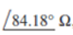 , inductive.
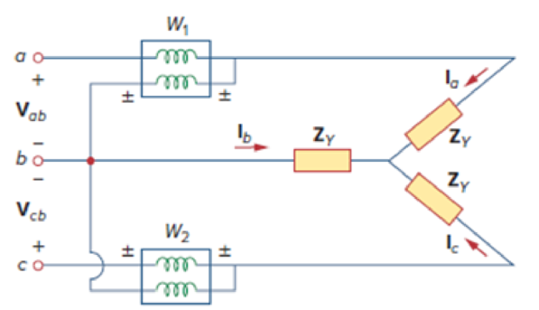
Figure 12.35
Two-wattmeter method applied to a balanced wye load.
Expert Solution & Answer
Want to see the full answer?
Check out a sample textbook solution
Students have asked these similar questions
Problem 2
For the system shown in Figure 12.5:
a) Find Is.
b) Find the average power delivered to each element.
c) Find the reactive power associated with each element.
d) Find PT, QT, and ST.
e) Find the power factor seen by the
source E.
R₁
ww
392
+
E = 50 V/60°
R3
ww
492
R₂
12 Ω Χ
16Ω
Xc
802
Figure 12.5
12. A certain load takes 300 kW at 400 V. A three phase capacitor bank rated 15 kVA per phase is connected
in parallel with the load to raise the power factor of the system to 90% lagging. What is the power factor of
the load before correction?
c. 92%
d. 88%
a. 99%
b. 95%
13. A 132 kV line three phase system delivers 70.7 MVA on a balanced delta connected load of a power factor
70.7% lagging. Determine the reactance necessary to attain unity power factor.
a. 1 092 ohms
c. 1142 ohms
d. 1 045 ohms
b. 965 ohms
14. A 150 kVA transformer bank will serve a load expected to draw 135 kW at 0.80 lagging power factor.
Solve for the size of the capacitor bank needed to be added in order to prevent overloading of the
transformer bank.
a 40.391 KVAR
d. 28.266 KVAR
a. 32.506 KVAR
b. 35.866 KVAR
1. What is the main direct cause of reactive power in AC system?
A. Resistance of transmission lines
B. Inductance and capacitance in the loads
C. Ideal transformer connected in the system
D. Power produced by generator
2. "Reactive power in a system is dissipated generally as thermal energy?"
A. TRUE
B. FALSE
3. Which of the following statements are correct for three phase circuit:
A. Sum of all the three phase currents is zero in unbalanced network
B. Total power transfer to load is constant with time
C. Neutral conductor is same size in terms of material used as in single phase conductors
D. Net apparent power consumed is equal to real power
Chapter 12 Solutions
Fundamentals of Electric Circuits
Ch. 12.2 - Given that Vbn=22030V, find Van and Vcn, assuming...Ch. 12.3 - A Y-connected balanced three-phase generator with...Ch. 12.4 - One line voltage of a balanced Y-connected source...Ch. 12.5 - A positive-sequence, balanced -connected source...Ch. 12.6 - In a balanced -Y circuit, Vab=44015 and ZY = (12 +...Ch. 12.7 - For the Y-Y circuit in Practice Prob. 12.2,...Ch. 12.7 - Calculate the line current required for a 30-kW...Ch. 12.7 - Assume that the two balanced loads in Fig....Ch. 12.8 - The unbalanced -load of Fig. 12.24 is supplied by...Ch. 12.8 - Find the line currents in the unbalanced...
Ch. 12.9 - Prob. 11PPCh. 12.9 - For the unbalanced circuit in Fig. 12.32, use...Ch. 12.10 - Repeat Example 12.13 for the network in Fig. 12.24...Ch. 12.10 - Let the line voltage VL = 208 V and the wattmeter...Ch. 12.10 - If the load in Fig. 12.35 is delta-connected with...Ch. 12 - What is the phase sequence of a three-phase motor...Ch. 12 - If in an acb phase sequence, , then Vcn is:Ch. 12 - Which of these is not a required condition for a...Ch. 12 - Prob. 4RQCh. 12 - Prob. 5RQCh. 12 - In a Y-Y system, a line voltage of 220 V produces...Ch. 12 - In a - system, a phase voltage of 100 V produces a...Ch. 12 - When a Y-connected load is supplied by voltages in...Ch. 12 - Prob. 9RQCh. 12 - Prob. 10RQCh. 12 - If Vab = 400 V in a balanced Y-connected...Ch. 12 - What is the phase sequence of a balanced...Ch. 12 - Given a balanced Y-connected three-phase generator...Ch. 12 - A three-phase system with abc sequence and VL =...Ch. 12 - For a Y-connected load, the time-domain...Ch. 12 - Using Fig. 12.41, design a problem to help other...Ch. 12 - Obtain the line currents in the three-phase...Ch. 12 - In a balanced three-phase Y-Y system, the source...Ch. 12 - A balanced Y-Y four-wire system has phase voltages...Ch. 12 - For the circuit in Fig. 12.43, determine the...Ch. 12 - In the Y- system shown in Fig. 12.44, the source...Ch. 12 - Using Fig. 12.45, design a problem to help other...Ch. 12 - In the balanced three-phase Y- system in Fig....Ch. 12 - Obtain the line currents in the three-phase...Ch. 12 - The circuit in Fig. 12.48 is excited by a balanced...Ch. 12 - A balanced delta-connected load has a phase...Ch. 12 - A positive sequence wye-connected source where ,...Ch. 12 - If Van = 22060 V in the network of Fig. 12.49,...Ch. 12 - For the - circuit of Fig. 12.50, calculate the...Ch. 12 - Prob. 20PCh. 12 - Three 440-V generators form a delta-connected...Ch. 12 - Find the line currents IaA, IbB, and IcC in the...Ch. 12 - A balanced delta connected source is connected to...Ch. 12 - A balanced delta-connected source has phase...Ch. 12 - In the circuit of Fig. 12.54, if , , , find the...Ch. 12 - Using Fig. 12.55, design a problem to help other...Ch. 12 - A -connected source supplies power to a...Ch. 12 - The line-to-line voltages in a Y-load have a...Ch. 12 - A balanced three-phase Y- system has V rms and Z =...Ch. 12 - In Fig. 12.56, the rms value of the line voltage...Ch. 12 - A balanced delta-connected load is supplied by a...Ch. 12 - Design a problem to help other students better...Ch. 12 - A three-phase source delivers 4.8 kVA to a...Ch. 12 - A balanced wye-connected load with a phase...Ch. 12 - Three equal impedances, 60 + j30 each, are...Ch. 12 - A 4200-V, three-phase transmission line has an...Ch. 12 - The total power measured in a three-phase system...Ch. 12 - Given the circuit in Fig. 12.57 below, find the...Ch. 12 - Find the real power absorbed by the load in Fig....Ch. 12 - For the three-phase circuit in Fig. 12.59, find...Ch. 12 - A balanced delta-connected load draws 5 kW at a...Ch. 12 - A balanced three-phase generator delivers 7.2 kW...Ch. 12 - Refer to Fig. 12.48. Obtain the complex power...Ch. 12 - A three-phase line has an impedance of 1 + j3 per...Ch. 12 - A balanced wye-connected load is connected to the...Ch. 12 - A three-phase load consists of three 100-...Ch. 12 - The following three parallel-connected three-phase...Ch. 12 - A balanced, positive-sequence wye-connected source...Ch. 12 - Each phase load consists of a 20- resistor and a...Ch. 12 - A balanced three-phase source with VL = 240 V rms...Ch. 12 - Consider the wye-delta system shown in Fig. 12.60....Ch. 12 - A four-wire wye-wye circuit has...Ch. 12 - Using Fig. 12.61, design a problem that will help...Ch. 12 - A balanced three-phase Y-source with VP = 880 V...Ch. 12 - A three-phase supply, with the line-to-line...Ch. 12 - Using Fig. 12.63, design a problem to help other...Ch. 12 - Determine the line currents for the three-phase...Ch. 12 - Solve Prob. 12.10 using PSpice or MultiSim. For...Ch. 12 - The source in Fig. 12.65 is balanced and exhibits...Ch. 12 - Use PSpice or MultiSim to determine Io in the...Ch. 12 - Given the circuit in Fig. 12.67, use PSpice or...Ch. 12 - Using Fig. 12.68, design a problem to help other...Ch. 12 - Use PSpice or MultiSim to find currents IaA and...Ch. 12 - For the circuit in Fig. 12.58, use PSpice or...Ch. 12 - A balanced three-phase circuit is shown in Fig....Ch. 12 - A three-phase, four-wire system operating with a...Ch. 12 - As shown in Fig. 12.72, a three-phase four-wire...Ch. 12 - Meter readings for a three-phase wye-connected...Ch. 12 - A certain store contains three balanced...Ch. 12 - The two-wattmeter method gives P1=1200W and...Ch. 12 - In Fig. 12.73, two wattmeters are properly...Ch. 12 - If wattmeters W1 and W2 are properly connected...Ch. 12 - For the circuit displayed in Fig. 12.74, find the...Ch. 12 - Predict the wattmeter readings for the circuit in...Ch. 12 - Prob. 75PCh. 12 - Show that the I2R losses will be higher for a...Ch. 12 - A three-phase generator supplied 10 kVA at a power...Ch. 12 - Prob. 78CPCh. 12 - A balanced three-phase generator has an abc phase...Ch. 12 - A balanced three-phase source furnishes power to...Ch. 12 - A professional center is supplied by a balanced...Ch. 12 - A balanced three-phase system has a distribution...Ch. 12 - A commercially available three-phase inductive...Ch. 12 - Figure 12.76 displays a three-phase...Ch. 12 - Design a three-phase heater with suitable...Ch. 12 - For the single-phase three-wire system in Fig....Ch. 12 - Consider the single-phase three-wire system shown...
Knowledge Booster


Learn more about
Need a deep-dive on the concept behind this application? Look no further. Learn more about this topic, electrical-engineering and related others by exploring similar questions and additional content below.Similar questions
- Three-phase electricity is delivered to a factory 7 km from a distribution company. The factory receives a total of 2000 kW of power at a voltage of 10.98 kV (rms) per phase. If the transmission cable in each phase has a resistance of 1.8 per 10 km, then the total power lost in the cables of this three-phase system is (a) 4.645 W (b) 13.93 W (c) 4.645 kW (d) 13.93 kWarrow_forwardTwo delta connected loads are connected in parallel and powered by a balanced Y-connectedsource. The smaller of two loads draws 10 kVA at a lagging power factor of 0.75 and the largerdraws 25 kVA at a leading power factor of 0.8. The line voltage is 400 V. Calculate a) The powerfactor at which the source is operating. b) The total power drawn by the two loads. c) The phasecurrent of each load.arrow_forwardGiven the circuit fed by 3 phases 380V phase to phase voltage, with 50HZ. a) Draw the power triangle of each of the loads (P, Q and S). b) Find the total equivalent (P, Q and S). c) Find the Value of Capacitor bank in order to have a unity power factor. d) Find the complex power supplied by the source after adding the capacitor bank. e) Explain why higher power factor is better for the installation 3 phases 380 v 50 Hz Load 1 Load 1 15 KVA 25 KVA 0.75 Lagging 0.85 Laggingarrow_forward
- 3- The single phase loads in the circuit can be described as follows: Load 1 absorbs an average power of 8-kW at a lagging power factor of 0.8, Load 2 absorbs 20-kVA leading power factor of 0.6, Load 3 absorbs 12-kVAr lagging power factor of 0.85. a) Determine the power factor of the three loads in parallel. b) Determine the apparent power required to supply the loads, the magnitude of the current, Is, and the average power loss in the transmission line. c) Determine the amplitude of source voltage Vs. 0.052 jo.502 12 V, 250LO'Vms L1 L2 L3arrow_forward5. The figure below shows two star connected loads with three phase power. The voltage source is 120Z0°. The loads are Z₁ = 10 + j4 № and Z₂ = 2 +j3 №. The cables are negligible. Calculate: a) the line and phase current. b) the real power from the source. c) the reactive power of the circuit. Is V N Z₁ Z₁ Z₁ Z₂ Z₂ N N Z₂arrow_forward1. Assume that a 2.5-kV 1-phase circuit feeds a load of 450 kW at a lagging load power factor and the load current of 215 A.If it is desired to improve the power factor determine the following. a. The new corrected p.f after installing a shunt capacitor unit with a rating of 350kvar. none 0.992 lag 0.9 lag 0.952 lagarrow_forward
- Consider a 10 kVA, 200/400 V, 50 HZ: single-phase tranformer has the folloving test results:0.C. test: 200 V, 0.6A, 63 W (L.V.side)S.C. test : 20 V, 25A, 85 W (H.V. side)Deternine:i- The eficiengy at 75 % offiull-load at 0.9 leading power factor.ii -The secondary terminal voltage on fill-load at tunity power factonarrow_forwardA load of 138+j460 Ohm is supplied through 3+j14 Ohm line as shown in Figure 1. (a) Find the average power dissipated in the line. (b) Find the value of capacitive reactance connected across the load to compensate the reactive power need of the load. (c) What is the equivalent impedance after compensation. (d) Find the average power dissipated in the line when the capacitive reactance is connected across the load. (e) Express the power loss in (d) as a percentage of the power found in (a) j14 Figure 1 7200/0 + V (rms) Source 3 wi Line Load 138 j460arrow_forward2. Three-Phase SystemThree loads are connected in parallel to a 12.47 kV, 60 Hz three-phase supply.Load 1: Inductive load, 60 kW and 660 KVARLoad 2: Capacitive load, 240 kW at 0.8 . power factorLoad 3: Resistive load 60 kWDefine:a. Active power, reactive power and total apparent power?b. Total power factor ?c. What is the total supply current?A Y-connected capacitor bank, connected in parallel withload, to improve the overall power factor to 0.95 lagging.Define:d. Total capacitor capacity (KVAR)?e. Capacitance of a phased capacitor (UF)?f. How big is the line current after the capacitor bank is installed?arrow_forward
- A 25 kVA, 240 V single phase source supply the rated power at the rated voltage to a motor at 0.8 power factor lagging. Find the capacitor bank in order to improve the power factor to 0.9 lagging connected to a motor.a. Calculate the real power, reactive power and current before capacitor bank is connected? b. Calculate the power and reactive power after capacitor bank is connected? c.What is kVA rating of capacitor bank QC?arrow_forwardFor an AC power distribution circuit, the line voltage is 480V and the line current is 53A. The circuit is balanced Delta connected. a. What is the phase voltage measured across each phase?b. What is the phase current for each phase?c. What is the total apparent power drawn by the circuit?d. What is the total apparent power drawn by each phase of the circuit?e. If the circuit has a Power Factor of 85%, what is the total real power drawn from the circuit?arrow_forward2) Figure shows three loads connected in parallel across a 1000-V (rms), 60-Hz single-phase source. Load 1: Inductive load, ... kVA, 0.28 p.f. lagging Load 2: Capacitive load, ... kW, 40 kvar Load 3: Resistive load, 15 kW Determine the total (a) kW, (b) kvar, (c) kva, and (d) supply power factor. (Please determine the power values within the specified limits: Load 1 apparent power: 100-150 kVA, Load 2 active power: 5-20 kW. By considering the power values you determined yourself, solve the question.) Load Load DE 1 2 Load 3arrow_forward
arrow_back_ios
SEE MORE QUESTIONS
arrow_forward_ios
Recommended textbooks for you
 Power System Analysis and Design (MindTap Course ...Electrical EngineeringISBN:9781305632134Author:J. Duncan Glover, Thomas Overbye, Mulukutla S. SarmaPublisher:Cengage Learning
Power System Analysis and Design (MindTap Course ...
Electrical Engineering
ISBN:9781305632134
Author:J. Duncan Glover, Thomas Overbye, Mulukutla S. Sarma
Publisher:Cengage Learning
What is the Difference Between Single Phase and Three Phase???; Author: Electrician U;https://www.youtube.com/watch?v=FEydcr4wJw0;License: Standard Youtube License