
Fundamentals of Electric Circuits
6th Edition
ISBN: 9780078028229
Author: Charles K Alexander, Matthew Sadiku
Publisher: McGraw-Hill Education
expand_more
expand_more
format_list_bulleted
Concept explainers
Videos
Textbook Question
Chapter 12, Problem 30P
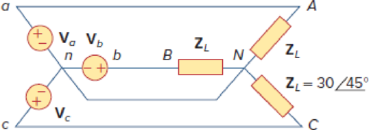
In Fig. 12.56, the rms value of the line voltage is 208 V. Find the average power delivered to the load.
Figure 12.56
For Prob. 12.30.
Expert Solution & Answer
Want to see the full answer?
Check out a sample textbook solution
Students have asked these similar questions
The standard unit of power factor of a 3-phase ac circuit is degrees.
Select one:
True
False
For the given circuit below
a. Calculate E, IR, and IL, in phasor form.b. Calculate the total power factor (leading or lagging) and the average power delivered to the circuit.c. Draw the admittance diagram and draw the phasor diagram of the currents Is, IR, and IL, and the voltage E.
12. For the following voltage and current phasors, calculate the complex power, apparent power, real power, and reactive power. Specify whether
the pf is leading or lagging.
a. V = 230/10° V rms, I = 0.52 - 60° Arms
b. V = 150/45° Vrms, I = 7.5/90°Arms
Chapter 12 Solutions
Fundamentals of Electric Circuits
Ch. 12.2 - Given that Vbn=22030V, find Van and Vcn, assuming...Ch. 12.3 - A Y-connected balanced three-phase generator with...Ch. 12.4 - One line voltage of a balanced Y-connected source...Ch. 12.5 - A positive-sequence, balanced -connected source...Ch. 12.6 - In a balanced -Y circuit, Vab=44015 and ZY = (12 +...Ch. 12.7 - For the Y-Y circuit in Practice Prob. 12.2,...Ch. 12.7 - Calculate the line current required for a 30-kW...Ch. 12.7 - Assume that the two balanced loads in Fig....Ch. 12.8 - The unbalanced -load of Fig. 12.24 is supplied by...Ch. 12.8 - Find the line currents in the unbalanced...
Ch. 12.9 - Prob. 11PPCh. 12.9 - For the unbalanced circuit in Fig. 12.32, use...Ch. 12.10 - Repeat Example 12.13 for the network in Fig. 12.24...Ch. 12.10 - Let the line voltage VL = 208 V and the wattmeter...Ch. 12.10 - If the load in Fig. 12.35 is delta-connected with...Ch. 12 - What is the phase sequence of a three-phase motor...Ch. 12 - If in an acb phase sequence, , then Vcn is:Ch. 12 - Which of these is not a required condition for a...Ch. 12 - Prob. 4RQCh. 12 - Prob. 5RQCh. 12 - In a Y-Y system, a line voltage of 220 V produces...Ch. 12 - In a - system, a phase voltage of 100 V produces a...Ch. 12 - When a Y-connected load is supplied by voltages in...Ch. 12 - Prob. 9RQCh. 12 - Prob. 10RQCh. 12 - If Vab = 400 V in a balanced Y-connected...Ch. 12 - What is the phase sequence of a balanced...Ch. 12 - Given a balanced Y-connected three-phase generator...Ch. 12 - A three-phase system with abc sequence and VL =...Ch. 12 - For a Y-connected load, the time-domain...Ch. 12 - Using Fig. 12.41, design a problem to help other...Ch. 12 - Obtain the line currents in the three-phase...Ch. 12 - In a balanced three-phase Y-Y system, the source...Ch. 12 - A balanced Y-Y four-wire system has phase voltages...Ch. 12 - For the circuit in Fig. 12.43, determine the...Ch. 12 - In the Y- system shown in Fig. 12.44, the source...Ch. 12 - Using Fig. 12.45, design a problem to help other...Ch. 12 - In the balanced three-phase Y- system in Fig....Ch. 12 - Obtain the line currents in the three-phase...Ch. 12 - The circuit in Fig. 12.48 is excited by a balanced...Ch. 12 - A balanced delta-connected load has a phase...Ch. 12 - A positive sequence wye-connected source where ,...Ch. 12 - If Van = 22060 V in the network of Fig. 12.49,...Ch. 12 - For the - circuit of Fig. 12.50, calculate the...Ch. 12 - Prob. 20PCh. 12 - Three 440-V generators form a delta-connected...Ch. 12 - Find the line currents IaA, IbB, and IcC in the...Ch. 12 - A balanced delta connected source is connected to...Ch. 12 - A balanced delta-connected source has phase...Ch. 12 - In the circuit of Fig. 12.54, if , , , find the...Ch. 12 - Using Fig. 12.55, design a problem to help other...Ch. 12 - A -connected source supplies power to a...Ch. 12 - The line-to-line voltages in a Y-load have a...Ch. 12 - A balanced three-phase Y- system has V rms and Z =...Ch. 12 - In Fig. 12.56, the rms value of the line voltage...Ch. 12 - A balanced delta-connected load is supplied by a...Ch. 12 - Design a problem to help other students better...Ch. 12 - A three-phase source delivers 4.8 kVA to a...Ch. 12 - A balanced wye-connected load with a phase...Ch. 12 - Three equal impedances, 60 + j30 each, are...Ch. 12 - A 4200-V, three-phase transmission line has an...Ch. 12 - The total power measured in a three-phase system...Ch. 12 - Given the circuit in Fig. 12.57 below, find the...Ch. 12 - Find the real power absorbed by the load in Fig....Ch. 12 - For the three-phase circuit in Fig. 12.59, find...Ch. 12 - A balanced delta-connected load draws 5 kW at a...Ch. 12 - A balanced three-phase generator delivers 7.2 kW...Ch. 12 - Refer to Fig. 12.48. Obtain the complex power...Ch. 12 - A three-phase line has an impedance of 1 + j3 per...Ch. 12 - A balanced wye-connected load is connected to the...Ch. 12 - A three-phase load consists of three 100-...Ch. 12 - The following three parallel-connected three-phase...Ch. 12 - A balanced, positive-sequence wye-connected source...Ch. 12 - Each phase load consists of a 20- resistor and a...Ch. 12 - A balanced three-phase source with VL = 240 V rms...Ch. 12 - Consider the wye-delta system shown in Fig. 12.60....Ch. 12 - A four-wire wye-wye circuit has...Ch. 12 - Using Fig. 12.61, design a problem that will help...Ch. 12 - A balanced three-phase Y-source with VP = 880 V...Ch. 12 - A three-phase supply, with the line-to-line...Ch. 12 - Using Fig. 12.63, design a problem to help other...Ch. 12 - Determine the line currents for the three-phase...Ch. 12 - Solve Prob. 12.10 using PSpice or MultiSim. For...Ch. 12 - The source in Fig. 12.65 is balanced and exhibits...Ch. 12 - Use PSpice or MultiSim to determine Io in the...Ch. 12 - Given the circuit in Fig. 12.67, use PSpice or...Ch. 12 - Using Fig. 12.68, design a problem to help other...Ch. 12 - Use PSpice or MultiSim to find currents IaA and...Ch. 12 - For the circuit in Fig. 12.58, use PSpice or...Ch. 12 - A balanced three-phase circuit is shown in Fig....Ch. 12 - A three-phase, four-wire system operating with a...Ch. 12 - As shown in Fig. 12.72, a three-phase four-wire...Ch. 12 - Meter readings for a three-phase wye-connected...Ch. 12 - A certain store contains three balanced...Ch. 12 - The two-wattmeter method gives P1=1200W and...Ch. 12 - In Fig. 12.73, two wattmeters are properly...Ch. 12 - If wattmeters W1 and W2 are properly connected...Ch. 12 - For the circuit displayed in Fig. 12.74, find the...Ch. 12 - Predict the wattmeter readings for the circuit in...Ch. 12 - Prob. 75PCh. 12 - Show that the I2R losses will be higher for a...Ch. 12 - A three-phase generator supplied 10 kVA at a power...Ch. 12 - Prob. 78CPCh. 12 - A balanced three-phase generator has an abc phase...Ch. 12 - A balanced three-phase source furnishes power to...Ch. 12 - A professional center is supplied by a balanced...Ch. 12 - A balanced three-phase system has a distribution...Ch. 12 - A commercially available three-phase inductive...Ch. 12 - Figure 12.76 displays a three-phase...Ch. 12 - Design a three-phase heater with suitable...Ch. 12 - For the single-phase three-wire system in Fig....Ch. 12 - Consider the single-phase three-wire system shown...
Knowledge Booster


Learn more about
Need a deep-dive on the concept behind this application? Look no further. Learn more about this topic, electrical-engineering and related others by exploring similar questions and additional content below.Similar questions
- 2. A load Z draws 12 kVA at a power factor of 0.856 lagging from a 120-V rms sinusoidal source. Calculate: (a) the average and reactive powers delivered to the load. (b) the peak current, and (c) the load impedance.arrow_forwardProblem 2 For the system shown in Figure 12.5: a) Find Is. b) Find the average power delivered to each element. c) Find the reactive power associated with each element. d) Find PT, QT, and ST. e) Find the power factor seen by the source E. R₁ ww 392 + E = 50 V/60° R3 ww 492 R₂ 12 Ω Χ 16Ω Xc 802 Figure 12.5arrow_forwardTwo loads are connected in parallel to a source of emf whose voltage is (110 + j63.5). if the branch currents are ?1= (8 – j8) & ?2= (7.5 + j10). Calculate the following items below. a. Total current b. Equivalent impedance c. Total power d. Reactive powerarrow_forward
- 1. What is the main direct cause of reactive power in AC system? A. Resistance of transmission lines B. Inductance and capacitance in the loads C. Ideal transformer connected in the system D. Power produced by generator 2. "Reactive power in a system is dissipated generally as thermal energy?" A. TRUE B. FALSE 3. Which of the following statements are correct for three phase circuit: A. Sum of all the three phase currents is zero in unbalanced network B. Total power transfer to load is constant with time C. Neutral conductor is same size in terms of material used as in single phase conductors D. Net apparent power consumed is equal to real powerarrow_forward5. The figure below shows two star connected loads with three phase power. The voltage source is 120Z0°. The loads are Z₁ = 10 + j4 № and Z₂ = 2 +j3 №. The cables are negligible. Calculate: a) the line and phase current. b) the real power from the source. c) the reactive power of the circuit. Is V N Z₁ Z₁ Z₁ Z₂ Z₂ N N Z₂arrow_forwardObtain the equivalent circuit of a 200/400 V, 50 Hz, single-phase transformcr from the following test data: O.C. test : 200 V, 0-7 A, 70 W .. on L.V. side S.C. test : 15 V, 10 A, 85 W Calculate the secondary voltage when delivering S kW at 08 p.f. lagging, the primary voltage being . on H.V. side 200 V. (R, = 57-14 Q ; X, = 330 2; R = 0-21 Q ; Xg, = 0-31 Q ; 3778 V)arrow_forward
- Consider a 10 kVA, 200/400 V, 50 HZ: single-phase tranformer has the folloving test results:0.C. test: 200 V, 0.6A, 63 W (L.V.side)S.C. test : 20 V, 25A, 85 W (H.V. side)Deternine:i- The eficiengy at 75 % offiull-load at 0.9 leading power factor.ii -The secondary terminal voltage on fill-load at tunity power factonarrow_forwardThree Impedances each of (8 - j24)2 are connected in mesh across a three-phase 420V ac supply. Determine the phase current, line current, active power, reactive power drawn from supply. Also draw the Phasor diagram for the mesh connection and marks the Line current ,phase current line voltage and phase angle between phase current and pahse voltage. phase current (Ip) Line current real power reactive powerarrow_forwarda. Y-Connected b. В 100kW Source 0.9 LAG 80KVA 0.8 LAG Figure 1 80kW 0.85 LAGarrow_forward
- 1. a) Find the rms magnitude and the phase angle of ICA in the circuit shown. 2. b) What percent of the average power delivered by the three-phase source is dissipated in the three-phase load?arrow_forwardpower factor of From a 120 URMS D A load draws 12 kVA at 0.86 lagging from a sinusuidal source calculate @ the average a. and reactive → the load load. (2) Peak current. Ⓒ load impedance. power delivered toarrow_forwardA 200 V single phase circuit has an apparent power of 5 KVA and reactive power of 4 KVAr. Then find (i) power factor (ii) impedance (iii) resistance (iv) reactance.arrow_forward
arrow_back_ios
SEE MORE QUESTIONS
arrow_forward_ios
Recommended textbooks for you
 Introductory Circuit Analysis (13th Edition)Electrical EngineeringISBN:9780133923605Author:Robert L. BoylestadPublisher:PEARSON
 Delmar's Standard Textbook Of ElectricityElectrical EngineeringISBN:9781337900348Author:Stephen L. HermanPublisher:Cengage Learning
 Programmable Logic ControllersElectrical EngineeringISBN:9780073373843Author:Frank D. PetruzellaPublisher:McGraw-Hill Education
 Fundamentals of Electric CircuitsElectrical EngineeringISBN:9780078028229Author:Charles K Alexander, Matthew SadikuPublisher:McGraw-Hill Education
 Electric Circuits. (11th Edition)Electrical EngineeringISBN:9780134746968Author:James W. Nilsson, Susan RiedelPublisher:PEARSON
 Engineering ElectromagneticsElectrical EngineeringISBN:9780078028151Author:Hayt, William H. (william Hart), Jr, BUCK, John A.Publisher:Mcgraw-hill Education,
Introductory Circuit Analysis (13th Edition)
Electrical Engineering
ISBN:9780133923605
Author:Robert L. Boylestad
Publisher:PEARSON
Delmar's Standard Textbook Of Electricity
Electrical Engineering
ISBN:9781337900348
Author:Stephen L. Herman
Publisher:Cengage Learning
Programmable Logic Controllers
Electrical Engineering
ISBN:9780073373843
Author:Frank D. Petruzella
Publisher:McGraw-Hill Education
Fundamentals of Electric Circuits
Electrical Engineering
ISBN:9780078028229
Author:Charles K Alexander, Matthew Sadiku
Publisher:McGraw-Hill Education
Electric Circuits. (11th Edition)
Electrical Engineering
ISBN:9780134746968
Author:James W. Nilsson, Susan Riedel
Publisher:PEARSON
Engineering Electromagnetics
Electrical Engineering
ISBN:9780078028151
Author:Hayt, William H. (william Hart), Jr, BUCK, John A.
Publisher:Mcgraw-hill Education,
What is the Difference Between Single Phase and Three Phase???; Author: Electrician U;https://www.youtube.com/watch?v=FEydcr4wJw0;License: Standard Youtube License