
Fundamentals of Electric Circuits
6th Edition
ISBN: 9780078028229
Author: Charles K Alexander, Matthew Sadiku
Publisher: McGraw-Hill Education
expand_more
expand_more
format_list_bulleted
Concept explainers
Videos
Textbook Question
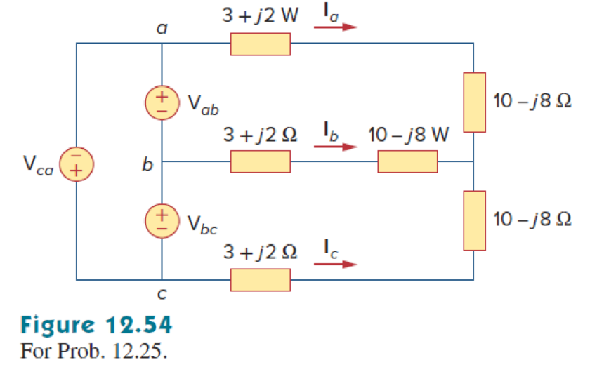
Chapter 12, Problem 25P
In the circuit of Fig. 12.54, if 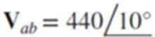 ,
, 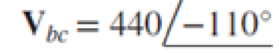 ,
, 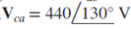 , find the currents.
Expert Solution & Answer
Want to see the full answer?
Check out a sample textbook solution
Students have asked these similar questions
A coil has an inductance of 39.8 microH and a series resistance of 20 ohms. Find its impedance at a frequency of 100 kHz and the current through the circuit if the voltage drop across the circuit is 80 V. Also find the voltage drop across the resistor u the voltage drop across the coil .
11. Two coupled coils have self-inductances L1 = 2 H and L2 = 0.5 H, and a coefficient of coupling K =
0.9. Determine the turns ratio N1/N2 of the two coils.
a. 2
b. 0.2
c. 0.5
d. 0.9
QA) The apparent power for an electric network was measured and found to be 360.6VAZ-56.34%
1. Determine the power factor of the network and sketch the power triangle.
2. Identify the elements of the network and provide a reason justifying your answer.
B) Define the permeability (ur) of the material. If you are required to design IH and I uH inductors,
what type of core will you use in your design and why? support your answer by equations.
Chapter 12 Solutions
Fundamentals of Electric Circuits
Ch. 12.2 - Given that Vbn=22030V, find Van and Vcn, assuming...Ch. 12.3 - A Y-connected balanced three-phase generator with...Ch. 12.4 - One line voltage of a balanced Y-connected source...Ch. 12.5 - A positive-sequence, balanced -connected source...Ch. 12.6 - In a balanced -Y circuit, Vab=44015 and ZY = (12 +...Ch. 12.7 - For the Y-Y circuit in Practice Prob. 12.2,...Ch. 12.7 - Calculate the line current required for a 30-kW...Ch. 12.7 - Assume that the two balanced loads in Fig....Ch. 12.8 - The unbalanced -load of Fig. 12.24 is supplied by...Ch. 12.8 - Find the line currents in the unbalanced...
Ch. 12.9 - Prob. 11PPCh. 12.9 - For the unbalanced circuit in Fig. 12.32, use...Ch. 12.10 - Repeat Example 12.13 for the network in Fig. 12.24...Ch. 12.10 - Let the line voltage VL = 208 V and the wattmeter...Ch. 12.10 - If the load in Fig. 12.35 is delta-connected with...Ch. 12 - What is the phase sequence of a three-phase motor...Ch. 12 - If in an acb phase sequence, , then Vcn is:Ch. 12 - Which of these is not a required condition for a...Ch. 12 - Prob. 4RQCh. 12 - Prob. 5RQCh. 12 - In a Y-Y system, a line voltage of 220 V produces...Ch. 12 - In a - system, a phase voltage of 100 V produces a...Ch. 12 - When a Y-connected load is supplied by voltages in...Ch. 12 - Prob. 9RQCh. 12 - Prob. 10RQCh. 12 - If Vab = 400 V in a balanced Y-connected...Ch. 12 - What is the phase sequence of a balanced...Ch. 12 - Given a balanced Y-connected three-phase generator...Ch. 12 - A three-phase system with abc sequence and VL =...Ch. 12 - For a Y-connected load, the time-domain...Ch. 12 - Using Fig. 12.41, design a problem to help other...Ch. 12 - Obtain the line currents in the three-phase...Ch. 12 - In a balanced three-phase Y-Y system, the source...Ch. 12 - A balanced Y-Y four-wire system has phase voltages...Ch. 12 - For the circuit in Fig. 12.43, determine the...Ch. 12 - In the Y- system shown in Fig. 12.44, the source...Ch. 12 - Using Fig. 12.45, design a problem to help other...Ch. 12 - In the balanced three-phase Y- system in Fig....Ch. 12 - Obtain the line currents in the three-phase...Ch. 12 - The circuit in Fig. 12.48 is excited by a balanced...Ch. 12 - A balanced delta-connected load has a phase...Ch. 12 - A positive sequence wye-connected source where ,...Ch. 12 - If Van = 22060 V in the network of Fig. 12.49,...Ch. 12 - For the - circuit of Fig. 12.50, calculate the...Ch. 12 - Prob. 20PCh. 12 - Three 440-V generators form a delta-connected...Ch. 12 - Find the line currents IaA, IbB, and IcC in the...Ch. 12 - A balanced delta connected source is connected to...Ch. 12 - A balanced delta-connected source has phase...Ch. 12 - In the circuit of Fig. 12.54, if , , , find the...Ch. 12 - Using Fig. 12.55, design a problem to help other...Ch. 12 - A -connected source supplies power to a...Ch. 12 - The line-to-line voltages in a Y-load have a...Ch. 12 - A balanced three-phase Y- system has V rms and Z =...Ch. 12 - In Fig. 12.56, the rms value of the line voltage...Ch. 12 - A balanced delta-connected load is supplied by a...Ch. 12 - Design a problem to help other students better...Ch. 12 - A three-phase source delivers 4.8 kVA to a...Ch. 12 - A balanced wye-connected load with a phase...Ch. 12 - Three equal impedances, 60 + j30 each, are...Ch. 12 - A 4200-V, three-phase transmission line has an...Ch. 12 - The total power measured in a three-phase system...Ch. 12 - Given the circuit in Fig. 12.57 below, find the...Ch. 12 - Find the real power absorbed by the load in Fig....Ch. 12 - For the three-phase circuit in Fig. 12.59, find...Ch. 12 - A balanced delta-connected load draws 5 kW at a...Ch. 12 - A balanced three-phase generator delivers 7.2 kW...Ch. 12 - Refer to Fig. 12.48. Obtain the complex power...Ch. 12 - A three-phase line has an impedance of 1 + j3 per...Ch. 12 - A balanced wye-connected load is connected to the...Ch. 12 - A three-phase load consists of three 100-...Ch. 12 - The following three parallel-connected three-phase...Ch. 12 - A balanced, positive-sequence wye-connected source...Ch. 12 - Each phase load consists of a 20- resistor and a...Ch. 12 - A balanced three-phase source with VL = 240 V rms...Ch. 12 - Consider the wye-delta system shown in Fig. 12.60....Ch. 12 - A four-wire wye-wye circuit has...Ch. 12 - Using Fig. 12.61, design a problem that will help...Ch. 12 - A balanced three-phase Y-source with VP = 880 V...Ch. 12 - A three-phase supply, with the line-to-line...Ch. 12 - Using Fig. 12.63, design a problem to help other...Ch. 12 - Determine the line currents for the three-phase...Ch. 12 - Solve Prob. 12.10 using PSpice or MultiSim. For...Ch. 12 - The source in Fig. 12.65 is balanced and exhibits...Ch. 12 - Use PSpice or MultiSim to determine Io in the...Ch. 12 - Given the circuit in Fig. 12.67, use PSpice or...Ch. 12 - Using Fig. 12.68, design a problem to help other...Ch. 12 - Use PSpice or MultiSim to find currents IaA and...Ch. 12 - For the circuit in Fig. 12.58, use PSpice or...Ch. 12 - A balanced three-phase circuit is shown in Fig....Ch. 12 - A three-phase, four-wire system operating with a...Ch. 12 - As shown in Fig. 12.72, a three-phase four-wire...Ch. 12 - Meter readings for a three-phase wye-connected...Ch. 12 - A certain store contains three balanced...Ch. 12 - The two-wattmeter method gives P1=1200W and...Ch. 12 - In Fig. 12.73, two wattmeters are properly...Ch. 12 - If wattmeters W1 and W2 are properly connected...Ch. 12 - For the circuit displayed in Fig. 12.74, find the...Ch. 12 - Predict the wattmeter readings for the circuit in...Ch. 12 - Prob. 75PCh. 12 - Show that the I2R losses will be higher for a...Ch. 12 - A three-phase generator supplied 10 kVA at a power...Ch. 12 - Prob. 78CPCh. 12 - A balanced three-phase generator has an abc phase...Ch. 12 - A balanced three-phase source furnishes power to...Ch. 12 - A professional center is supplied by a balanced...Ch. 12 - A balanced three-phase system has a distribution...Ch. 12 - A commercially available three-phase inductive...Ch. 12 - Figure 12.76 displays a three-phase...Ch. 12 - Design a three-phase heater with suitable...Ch. 12 - For the single-phase three-wire system in Fig....Ch. 12 - Consider the single-phase three-wire system shown...
Additional Engineering Textbook Solutions
Find more solutions based on key concepts
Identify the type of input and output configuration for each diff-amp in Figure 18-35.
Electronics Fundamentals: Circuits, Devices & Applications
Find I0 and I1 in the circuit in Fig.P2.12.
Basic Engineering Circuit Analysis
A constant voltage of 10V is applied to a 50H inductance, as shown in Figure P3.51 Figure P3 51 The current in ...
Electrical Engineering: Principles & Applications (7th Edition)
When travelers from the USA and Canada visit Europe, they encounter a different power distribution system. Wall...
Electric machinery fundamentals
Three point charges of equal magnitude q, that will yield a zero net electric field at the origin.
Engineering Electromagnetics
Assume a telephone signal travels through a cable at two-thirds the speed of light. How long does it take the s...
Electric Circuits (10th Edition)
Knowledge Booster


Learn more about
Need a deep-dive on the concept behind this application? Look no further. Learn more about this topic, electrical-engineering and related others by exploring similar questions and additional content below.Similar questions
- The following expressions represent the instantaneous values of e.m.f. in three coils connected in series. ₁ = 50 sin cor e₂ = 40 sin (wt + 60°) = 60 sin (oot - 30°) Find an expression for the resultant e.m.f. when coils are connected to give the sum of c.m.f.s.arrow_forwardsolve for current i :arrow_forwardFind the current I1 and the charge stored in capacitor C2 for steady state.arrow_forward
- B-Two practical coils with internal resistances of R1, R2 has quality factors of Q1& Q2 respectively. If these two coils are connected in series find the resultant quality factor. ... ..arrow_forwardPlease answer this NEATLY, COMPLETELY, and CORRECTLY for an UPVOTE. For the following pairs of voltage and current, indicate their phase relationship (e.g. v leads i by 10°). Analyze whether the element involved in each pair is a resistor, inductor, or capacitor. Also obtain the value of R, L, and C if sufficient data are given.arrow_forwardPlease answer this NEATLY, COMPLETELY, and CORRECTLY for an UPVOTE. For the following pairs of voltage and current, indicate their phase relationship (e.g. v leads i by 10°). Analyze whether the element involved in each pair is a resistor, inductor, capacitor or a combination. Also obtain the value of R, L, and C if sufficient data are given.arrow_forward
- Calculate the reactance of a coil of inductance 0.2H when it is connected to a 50Hz supply. A. 62.83ohms B. 63.82ohms C. 62.38ohms D. 63.28ohmsarrow_forward1. A coil has a resistance of 18 ohm when its mean temperature is 20 °C and of 20 ohm when its mean temperature is 50°C . Find the mean temperature rise when its resistance is 21 ohm and the surroundings isn15 °C.arrow_forwardPls help ASAP. The subject is Electric Networksarrow_forward
- Two coils A and B known to have the same resistance are connected in series across a 110-V, 60-cycle line. The current and power delivered by the source are respectively 4.1 A and 300 W. If the voltage across coil A is twice that across coil B, calculate the inductance of coil B. A. 8.63 mH B. 7.36 mH C. 9.02 mH D. 4.49 mHarrow_forwardElectrical equipment in an office takes a current of 13 A from a 240 V supply. Estimate the cost per week of electricity if the equipment is used for 30 hours each week and 1kW-Hr of energy costs is P12.50.arrow_forward11. a capacitor, resistor of 10 ohms, and an inductor of 70 mH are in series with an ac source marked 120 V, 70 Hz. if it is found that the voltage is in phase with the current, then find out the impedance of the circuit a. 900 ohms b. 100 ohms c. 10 ohms d. 5 ohmsarrow_forward
arrow_back_ios
SEE MORE QUESTIONS
arrow_forward_ios
Recommended textbooks for you
 Introductory Circuit Analysis (13th Edition)Electrical EngineeringISBN:9780133923605Author:Robert L. BoylestadPublisher:PEARSON
 Delmar's Standard Textbook Of ElectricityElectrical EngineeringISBN:9781337900348Author:Stephen L. HermanPublisher:Cengage Learning
 Programmable Logic ControllersElectrical EngineeringISBN:9780073373843Author:Frank D. PetruzellaPublisher:McGraw-Hill Education
 Fundamentals of Electric CircuitsElectrical EngineeringISBN:9780078028229Author:Charles K Alexander, Matthew SadikuPublisher:McGraw-Hill Education
 Electric Circuits. (11th Edition)Electrical EngineeringISBN:9780134746968Author:James W. Nilsson, Susan RiedelPublisher:PEARSON
 Engineering ElectromagneticsElectrical EngineeringISBN:9780078028151Author:Hayt, William H. (william Hart), Jr, BUCK, John A.Publisher:Mcgraw-hill Education,
Introductory Circuit Analysis (13th Edition)
Electrical Engineering
ISBN:9780133923605
Author:Robert L. Boylestad
Publisher:PEARSON
Delmar's Standard Textbook Of Electricity
Electrical Engineering
ISBN:9781337900348
Author:Stephen L. Herman
Publisher:Cengage Learning
Programmable Logic Controllers
Electrical Engineering
ISBN:9780073373843
Author:Frank D. Petruzella
Publisher:McGraw-Hill Education
Fundamentals of Electric Circuits
Electrical Engineering
ISBN:9780078028229
Author:Charles K Alexander, Matthew Sadiku
Publisher:McGraw-Hill Education
Electric Circuits. (11th Edition)
Electrical Engineering
ISBN:9780134746968
Author:James W. Nilsson, Susan Riedel
Publisher:PEARSON
Engineering Electromagnetics
Electrical Engineering
ISBN:9780078028151
Author:Hayt, William H. (william Hart), Jr, BUCK, John A.
Publisher:Mcgraw-hill Education,
What is the Difference Between Single Phase and Three Phase???; Author: Electrician U;https://www.youtube.com/watch?v=FEydcr4wJw0;License: Standard Youtube License