
Concept explainers
Videos
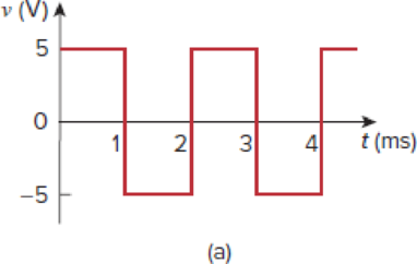
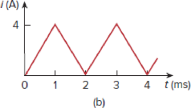
A square-wave generator produces the voltage waveform shown in Fig. 6.94(a). What kind of a circuit component is needed to convert the voltage waveform to the triangular current waveform shown in Fig. 6.94(b)? Calculate the value of the component, assuming that it is initially uncharged.
Figure 6.94
For Prob. 6.85.
Find the circuit component that is needed to convert the voltage waveform into the triangular current waveform and to calculate the value of the circuit component.
Answer to Problem 85CP
The circuit component inductor is needed to convert the given voltage waveform into the triangular current waveform and the value for the inductor
Explanation of Solution
Given data:
Refer to Figure 6.94 in the textbook.
Formula used:
Write the expression to calculate the straight line equation for two points
Refer to Figure 6.94(b) in the textbook.
From the given graph, substitute
Calculation:
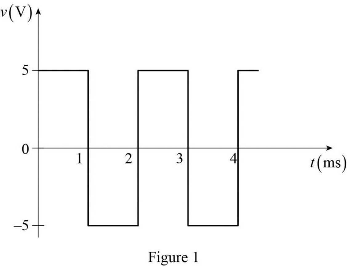
The given voltage waveform is redrawn as Figure 1.
The given triangular current waveform is redrawn as Figure 2.
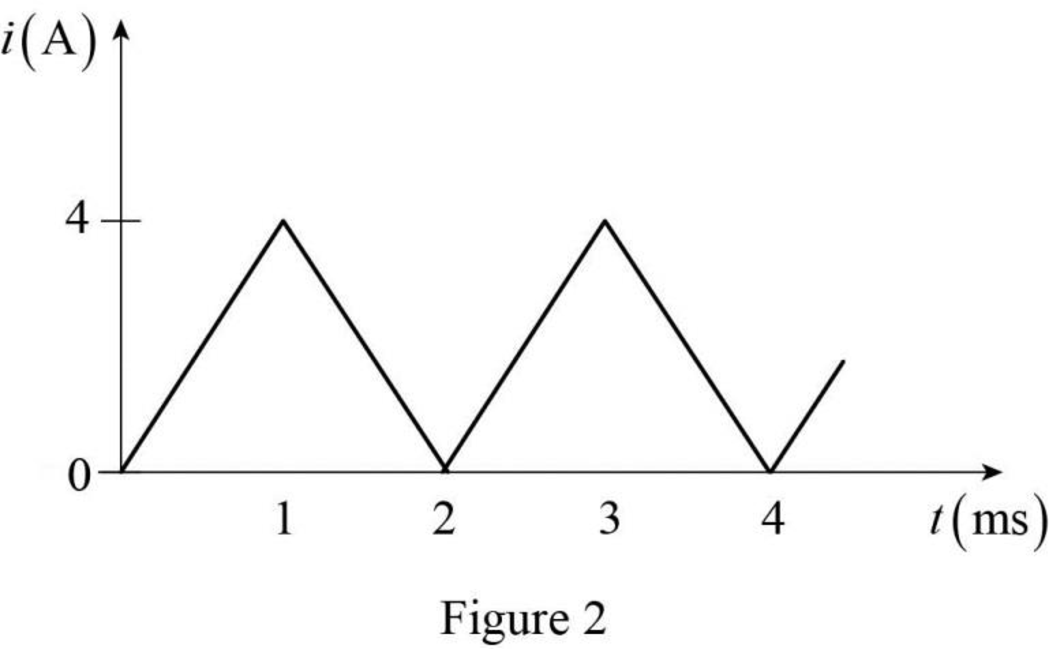
Refer to Figure 1 and Figure 2. Generally, integration of the square waveform gives the triangular waveform. That is, the integration of the voltage waveform gives the current waveform. Such relation can be obtained in following relation.
Here,
Refer to equation (3), the circuit component inductor is needed to convert the square voltage waveform to the triangular current waveform.
Differentiate the equation (3) with respect to
Rearrange the above equation to find
Refer to Figure 1. The voltage function is expressed as,
Refer to Figure 2, split up the time period as four divisions
Case (i):
The two points
Substitute
Simplify the equation to find
Case (ii):
The two points
Substitute
Simplify the equation to find
Case (iii):
The two points
Substitute
Simplify the equation to find
Case (iv):
The two points
Substitute
Simplify the equation to find
Therefore, the current function of the signal in Figure 2 is,
For
Substitute
For
Substitute
For
Substitute
For
Substitute
Therefore, the voltage function of the Figure 2 is expressed as,
The voltage function of the signal in Figure 1 is equal to the voltage function that is obtained in equation (6).
Compare the equations (5) and (6) for any of the time limits. Assume the comparison is made for
Rearrange the above equation to find
Therefore, the circuit component inductor is needed to convert the given voltage waveform into the triangular current waveform and the value for the inductor
Conclusion:
Thus, the circuit component inductor is needed to convert the given voltage waveform into the triangular current waveform and the value for the inductor
Want to see more full solutions like this?
Chapter 6 Solutions
Fundamentals of Electric Circuits


- The current in a 0.6 microfarad capacitor is 0 [A] for time less than zero and 3cos50000t [A] for time greater than or equal to zero. Find v(t) and the maximum power delivered to the capacitor.arrow_forward2. Suppose you want a capacitor bank with a total capacitance of 0.750 F and you possess numerous 1.50 mF capacitors. What is the smallest number you could hook together to achieve your goal, and how would you connect them?arrow_forwardThe current I(t) through a 5.0-mH inductor varies with time, as shown below. The resistance of the inductor is 5.0 Ω. Calculate the voltage across the inductor at t = 2.0 ms, t = 4.0 ms, and t = 8.0 ms .arrow_forward
- Three capacitors connected in a series having the capacitance of 4 mF, 10 mF, and 12 mF. What will be equivalent capacitance in (mF).arrow_forward. A capacitor has a charge of 20.5 C when connected with a 24V battery. Determine the capacitance.arrow_forwardAn inductor is connected to a 240=v, 1000-hz line. the circuit current is 0.6A what is the inductance of the inductorarrow_forward
- The voltage source is at a constant level for a long time, which we approximate as infinite. This is the circuit: The voltage drop across the capacitor rises from 0 to ℰ. Note that ℰ is never actually known in the measurement. In fact, the oscilloscope voltage is decalibrated, so that, whatever ℰ is, ℰ is at the top line while zero is at the bottom line. We don't measure voltage levels, but rather 1/2, 1/4, and 1/8 the maximum. Kirchhoff's voltage law give: ℰ = IR + Q/C or the following: dQdt=−1RC(Q−EC)dQdt=−1RC(Q−ℰC) The solution for the capacitor voltage is VC(t)=E(1−e−t/RC)VC(t)=ℰ(1−e−t/RC) The voltage is zero at t = 0, t is the rising time, and you have to know when the rising begins.arrow_forward4. Find the equivalent capacitance with respect to the terminals a, barrow_forwardThree capacitors have ratings of 20 µF, 60 µF, and 30 µF, respectively. These capacitors are connected in parallel across a 220 V DC source. Determine: the total capacitance of the three capacitors connected in parallel. the total charge, in coulombs, taken by the three capacitors in parallel when connected across a 220 V DC sourcearrow_forward
- The R-L Circuit: An inductor with an inductance of 2.50 H and a resistance of 7.00 n is connected to the terminals ofa battery with an emf of 6.00 V and an internal resistance of 1.00 n. What is the rate ofincrease of current at the instant when the current is 0.500 A? A) 0.8 A/s B) 0.6 A/s C) 0.4 A/s D) zero E) None of the above.arrow_forwardA capacitor is made of 2 rectangular metal plates with side length of 3cmx6cm separated by a distance of 2.36 with water in between the plates. The capacitor has a voltage of 110v and is not connected to a battery. Calculate the capacitance. What is the new capacitance if we replace water with a new dielectric material with a constant of 3.75 in between the plates? What is the new voltage? What is the charge on each plate?arrow_forwardIf the current through a 10-mH inductor increases from zero to 2 A, how much energy is stored in the inductorarrow_forward
 Introductory Circuit Analysis (13th Edition)Electrical EngineeringISBN:9780133923605Author:Robert L. BoylestadPublisher:PEARSON
 Delmar's Standard Textbook Of ElectricityElectrical EngineeringISBN:9781337900348Author:Stephen L. HermanPublisher:Cengage Learning
 Programmable Logic ControllersElectrical EngineeringISBN:9780073373843Author:Frank D. PetruzellaPublisher:McGraw-Hill Education
 Fundamentals of Electric CircuitsElectrical EngineeringISBN:9780078028229Author:Charles K Alexander, Matthew SadikuPublisher:McGraw-Hill Education
 Electric Circuits. (11th Edition)Electrical EngineeringISBN:9780134746968Author:James W. Nilsson, Susan RiedelPublisher:PEARSON
 Engineering ElectromagneticsElectrical EngineeringISBN:9780078028151Author:Hayt, William H. (william Hart), Jr, BUCK, John A.Publisher:Mcgraw-hill Education,