
Fundamentals of Electric Circuits
6th Edition
ISBN: 9780078028229
Author: Charles K Alexander, Matthew Sadiku
Publisher: McGraw-Hill Education
expand_more
expand_more
format_list_bulleted
Concept explainers
Videos
Textbook Question
Chapter 6, Problem 28P
Obtain the equivalent capacitance of the network shown in Fig. 6.60.
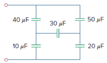
Figure 6.60
For Prob. 6.28.
Expert Solution & Answer
Want to see the full answer?
Check out a sample textbook solution
Students have asked these similar questions
The voltage across a 200-mH inductor is given by v = 3t2 + 2t + 4V. Determine the current through the inductor after 1s. Assume that i(0) = 0
An 8 mH inductor and a 2omega resistor are in series with a 20V battery. The switch is closed for t=0 at which the current is 0.
Determine the potential across the inductor and across the resistor.
6. The total capacitance of two 40-mF series-connected capacitors in parallel with a
70-mF capacitor is?
Chapter 6 Solutions
Fundamentals of Electric Circuits
Ch. 6.2 - What is the voltage across a 4.5-F capacitor if...Ch. 6.2 - If a 10-F capacitor is connected to a voltage...Ch. 6.2 - The current through a 100-F capacitor is i(t) = 50...Ch. 6.2 - Figure 6.11 For Practice Prob. 6.4. An initially...Ch. 6.2 - Under dc conditions, find the energy stored in the...Ch. 6.3 - Find the equivalent capacitance seen at the...Ch. 6.3 - Find the voltage across each of the capacitors in...Ch. 6.4 - If the current through a 1-mH inductor is i(t) =...Ch. 6.4 - The terminal voltage of a 2-H inductor is v = 10(1...Ch. 6.4 - Determine vC, iL, and the energy stored in the...
Ch. 6.5 - Calculate the equivalent inductance for the...Ch. 6.5 - In the circuit of Fig. 6.34, i1(t) = 3e2t A. If...Ch. 6.6 - The integrator in Fig. 6.35(b) has R = 100 k, C =...Ch. 6.6 - The differentiator in Fig. 6.37 has R = 100 k and...Ch. 6.6 - Design an analog computer circuit to solve the...Ch. 6 - What charge is on a 5-F capacitor when it is...Ch. 6 - Capacitance is measured in: (a)coulombs (b)joules...Ch. 6 - When the total charge in a capacitor is doubled,...Ch. 6 - Can the voltage waveform in Fig. 6.42 be...Ch. 6 - The total capacitance of two 40-mF...Ch. 6 - In Fig. 6.43, if i = cos 4t and v = sin 4t, the...Ch. 6 - A 5-H inductor changes its current by 3 A in 0.2...Ch. 6 - If the current through a 10-mH inductor increases...Ch. 6 - Inductors in parallel can be combined just like...Ch. 6 - Prob. 10RQCh. 6 - If the voltage across a 7.5-F capacitor is 2te3t...Ch. 6 - A 50-F capacitor has energy w(t) = 10 cos2 377t J....Ch. 6 - Design a problem to help other students better...Ch. 6 - A voltage across a capacitor is equal to [2 2...Ch. 6 - The voltage across a 4-F capacitor is shown in...Ch. 6 - The voltage waveform in Fig. 6.46 is applied...Ch. 6 - At t = 0, the voltage across a 25-mF capacitor is...Ch. 6 - A 4-mF capacitor has the terminal voltage v=...Ch. 6 - The current through a 0.5-F capacitor is 6(1 et)...Ch. 6 - The voltage across a 5-mF capacitor is shown in...Ch. 6 - A 4-mF capacitor has the current waveform shown in...Ch. 6 - A voltage of 45e2000t V appears across a parallel...Ch. 6 - Find the voltage across the capacitors in the...Ch. 6 - Series-connected 20- and 60-pF capacitors are...Ch. 6 - Two capacitors (25 and 75 F) are connected to a...Ch. 6 - The equivalent capacitance at terminals a-b in the...Ch. 6 - Determine the equivalent capacitance for each of...Ch. 6 - Find Ceq in the circuit of Fig. 6.52 if all...Ch. 6 - Find the equivalent capacitance between terminals...Ch. 6 - Find the equivalent capacitance at terminals a-b...Ch. 6 - Determine the equivalent capacitance at terminals...Ch. 6 - Obtain the equivalent capacitance of the circuit...Ch. 6 - Using Fig. 6.57, design a problem that will help...Ch. 6 - In the circuit shown in Fig. 6.58 assume that the...Ch. 6 - (a)Show that the voltage-division rule for two...Ch. 6 - Three capacitors, C1 = 5 F, C2 = 10 F, and C3 = 20...Ch. 6 - Given that four 10-F capacitors can be connected...Ch. 6 - Obtain the equivalent capacitance of the network...Ch. 6 - Determine Ceq for each circuit in Fig. 6.61....Ch. 6 - Assuming that the capacitors are initially...Ch. 6 - If v(0) = 0, find v(t), i1(t), and i2(t) in the...Ch. 6 - In the circuit in Fig. 6.64, let is = 4.5e2t mA...Ch. 6 - Obtain the Thevenin equivalent at the terminals,...Ch. 6 - The current through a 25-mH inductor is 10et/2 A....Ch. 6 - An inductor has a linear change in current from...Ch. 6 - Design a problem to help other students better...Ch. 6 - The current through a 12-mH inductor is 4 sin 100t...Ch. 6 - The current through a 40-mH inductor is i(t)= 0,...Ch. 6 - The voltage across a 50-mH inductor is given by...Ch. 6 - The current through a 5-mH inductor is shown in...Ch. 6 - The voltage across a 2-H inductor is 20(1 e2t) V....Ch. 6 - If the voltage waveform in Fig. 6.67 is applied...Ch. 6 - The current in a 150-mH inductor increases from 0...Ch. 6 - A 100-mH inductor is connected in parallel with a...Ch. 6 - If the voltage waveform in Fig. 6.68 is applied to...Ch. 6 - Find vC, iL, and the energy stored in the...Ch. 6 - For the circuit in Fig. 6.70, calculate the value...Ch. 6 - Under steady-state dc conditions, find i and v in...Ch. 6 - Find the equivalent inductance of the circuit in...Ch. 6 - An energy-storage network consists of...Ch. 6 - Determine Leq at terminals a-b of the circuit in...Ch. 6 - Using Fig. 6.74, design a problem to help other...Ch. 6 - Find Leq at the terminals of the circuit in Fig....Ch. 6 - Find the equivalent inductance looking into the...Ch. 6 - Find Leq in each of the circuits in Fig. 6.77....Ch. 6 - Find Leq in the circuit of Fig. 6.78. Figure 6.78...Ch. 6 - Determine Leq that may be used to represent the...Ch. 6 - The current waveform in Fig. 6.80 flows through a...Ch. 6 - (a) For two inductors in series as in Fig....Ch. 6 - In the circuit of Fig. 6.82, io(0) = 2 A....Ch. 6 - Consider the circuit in Fig. 6.83. Find: (a) Leq,...Ch. 6 - Consider the circuit in Fig. 6.84. Given that v(t)...Ch. 6 - In the circuit of Fig. 6.85, sketch vo. Figure...Ch. 6 - The switch in Fig. 6.86 has been in position A for...Ch. 6 - The inductors in Fig. 6.87 are initially charged...Ch. 6 - The current i(t) through a 20-mH inductor is...Ch. 6 - An op amp integrator has R = 50 k and C = 0.04 F....Ch. 6 - A 6-V dc voltage is applied to an integrator with...Ch. 6 - An op amp integrator with R = 4 M and C = 1 F has...Ch. 6 - Using a single op amp, a capacitor, and resistors...Ch. 6 - Show how you would use a single op amp to generate...Ch. 6 - At t = 1.5 ms, calculate vo due to the cascaded...Ch. 6 - Show that the circuit in Fig. 6.90 is a...Ch. 6 - The triangular waveform in Fig. 6.91(a) is applied...Ch. 6 - An op amp differentiator has R = 250 k and C = 10...Ch. 6 - A voltage waveform has the following...Ch. 6 - The output vo of the op amp circuit in Fig....Ch. 6 - Prob. 78PCh. 6 - Figure 6.93 presents an analog computer designed...Ch. 6 - Design an analog computer to simulate the...Ch. 6 - Design an op amp circuit such that vo=10vs+2vsdt...Ch. 6 - Your laboratory has available a large number of...Ch. 6 - An 8-mH inductor is used in a fusion power...Ch. 6 - A square-wave generator produces the voltage...Ch. 6 - An electric motor can be modeled as a series...
Knowledge Booster


Learn more about
Need a deep-dive on the concept behind this application? Look no further. Learn more about this topic, electrical-engineering and related others by exploring similar questions and additional content below.Similar questions
- Determine the energy stored in the 6μc capacitor in the capacitor circuit in the figure.arrow_forwardA capacitor is made of 2 rectangular metal plates with side length of 3cmx6cm separated by a distance of 2.36cm with water in between the plates. The capacitor has a voltage of 110v and is not connected to a battery. Calculate the capacitance. What is the new capacitance if we replace water with a new dielectric material with a constant of 3.75 in between the plates? What is the new voltage? What is the charge on each plate? Follow this format- Given: Required: Equtions: Solution: Answer:arrow_forwardPlease draw the problem and answer, thanks for the help. A capacitor is made of 2 rectangular metal plates with side length of 3 cm x 6 cm separated by a distance of 2.36 cm with water in between the plates. The capacitor has a voltage of 110 v and is not connected to a battery. Calculate the capacitance. What is the new capacitance if we replace water with a new dielectric material with a constant of 3.75 in between the plates? What is the new voltage? What is the charge on each plate?arrow_forward
- two capacitors with capacitances of 1.22uF and 6.87uF are connected in parallel. These are connected to a 48V battery . How much energy will be stored in the 6.87uF capacitor in mJ? Please do fast ASAParrow_forwardWhich of the following statement is false O A capacitor cannot store energy if the current through the capacitor is zero. The current flows through an inductor cannot be changed in zero time. O The voltage across a capacitor cannot be changed in zero time. An inductor is a short circuit to DC.arrow_forwardA 20-mH inductor and a 18-mH inductor are connected in series with a 3-A current source. Find (a) the equivalent inductance and (b) the total energy stored. (a) mH (b) mJarrow_forward
- R = 91 ohm L = 93 H C = 3 mF Can you please find the equation for the voltage across the capacitor ..arrow_forwardThe initial voltage drop across capacitor is 40V and R-500 Ohm Find the current ic(0+).arrow_forwardThe illustration shows four capacitors that are connected together in a so-called capacitor bridge. Initially, the capacitors are uncharged. Which relationship must hold between the four capacitances so that the voltage between points c and d remains zero when a voltage U is applied between points a and b?arrow_forward
- A 2002 resistor, a 0.01 H inductor and a 100 µF capacitor are connected in series, A DC voltage of 100 V is suddenly applied to the circuit. Find the maximum current and the time at which it occurs.arrow_forwardThe current through a 10-mH inductor is 10e-12 A. Find the voltage and the power at t = 2 s. The voltage is The power is mV mW Aarrow_forwardA 0.8H inductor is connected in series with a 7.0ohm resistor. If the connection is enegized form a 10-V DC source, determine the voltage(in volts) across the inductor at t = 2.5ms/ The initial current is 150mA.arrow_forward
arrow_back_ios
SEE MORE QUESTIONS
arrow_forward_ios
Recommended textbooks for you
 Introductory Circuit Analysis (13th Edition)Electrical EngineeringISBN:9780133923605Author:Robert L. BoylestadPublisher:PEARSON
 Delmar's Standard Textbook Of ElectricityElectrical EngineeringISBN:9781337900348Author:Stephen L. HermanPublisher:Cengage Learning
 Programmable Logic ControllersElectrical EngineeringISBN:9780073373843Author:Frank D. PetruzellaPublisher:McGraw-Hill Education
 Fundamentals of Electric CircuitsElectrical EngineeringISBN:9780078028229Author:Charles K Alexander, Matthew SadikuPublisher:McGraw-Hill Education
 Electric Circuits. (11th Edition)Electrical EngineeringISBN:9780134746968Author:James W. Nilsson, Susan RiedelPublisher:PEARSON
 Engineering ElectromagneticsElectrical EngineeringISBN:9780078028151Author:Hayt, William H. (william Hart), Jr, BUCK, John A.Publisher:Mcgraw-hill Education,
Introductory Circuit Analysis (13th Edition)
Electrical Engineering
ISBN:9780133923605
Author:Robert L. Boylestad
Publisher:PEARSON
Delmar's Standard Textbook Of Electricity
Electrical Engineering
ISBN:9781337900348
Author:Stephen L. Herman
Publisher:Cengage Learning
Programmable Logic Controllers
Electrical Engineering
ISBN:9780073373843
Author:Frank D. Petruzella
Publisher:McGraw-Hill Education
Fundamentals of Electric Circuits
Electrical Engineering
ISBN:9780078028229
Author:Charles K Alexander, Matthew Sadiku
Publisher:McGraw-Hill Education
Electric Circuits. (11th Edition)
Electrical Engineering
ISBN:9780134746968
Author:James W. Nilsson, Susan Riedel
Publisher:PEARSON
Engineering Electromagnetics
Electrical Engineering
ISBN:9780078028151
Author:Hayt, William H. (william Hart), Jr, BUCK, John A.
Publisher:Mcgraw-hill Education,
Capacitors Explained - The basics how capacitors work working principle; Author: The Engineering Mindset;https://www.youtube.com/watch?v=X4EUwTwZ110;License: Standard YouTube License, CC-BY