
Concept explainers
Videos
(a) For two inductors in series as in Fig. 6.81(a), show that the voltage division principle is
assuming that the initial conditions are zero.
(b) For two inductors in parallel as in Fig. 6.81(b), show that the current-division principle is
assuming that the initial conditions are zero.
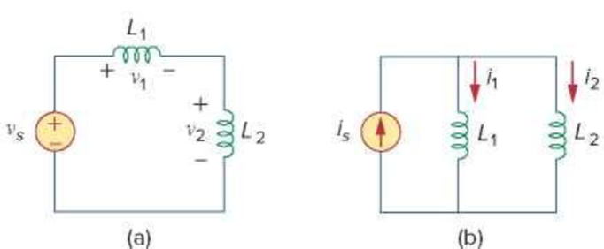
Figure 6.81
For Prob. 6.59.
Want to see the full answer?
Check out a sample textbook solution
Chapter 6 Solutions
Fundamentals of Electric Circuits


- 5. A 0.05-µF capacitor is connected in parallel with a 10-nF capacitor. How much capacitance must be connected in parallel with this combination if the total capacitance is to be 100-nF?arrow_forwardWe connect a 6 uF capacitor to the terminals of a 12 V battery, leaving it for a long time. Once the capacitor is fully charged, we remove the 12 V battery. Next, we connect the positive plate of the capacitor to the positive terminal of a 6 V battery, and the negative plate of the capacitor to the battery's negative terminal. At the moment the capacitor is connected to the 6 V battery, draw the new circuit. Indicate which plate of the capacitor is positive/negative and the direction of current flow, Calculate the current in the circuit or explain why you can't if it's not possible. Either way, give some qualitative description of what happens. Hint: where is the resistance in a DC circuit without a resistor?arrow_forward5. A series combination of an 18.0 mF capacitor and a resistor are connected to a 125 V battery. After three seconds, the voltage across the capacitor is 49.5 V. (a) What is the resistance of the resistor? (b) If at that three second mark the battery is subsequently removed and the capacitor is allowed to discharge through the resistor then how many excess electrons will remain on the capacitor at the five second mark?arrow_forward
- 57. A capacitor of capacitance 2 µF is charged to a potential difference of 200 V. After disconnecting from the battery, it is con- nected in parallel with another uncharged capacitor. The common potential is 40 V. The capacitance of the second capacitor is (i) 6 µF (ii) 12 µF (iii) 8 µF (iv) 16 µFarrow_forwardYou have two identical capacitors, each of which can hold charge Q, when it has a 6 V potential across it. You construct a circuit with the two capacitors in series connected to a 12 V battery. Which of the following is true? O each capacitor will end up with a charge of Q1 O each capacitor will end up with a charge of 2Q1 O each capacitor will end up with 3 V across it O each capacitor will end up with 12 V across itarrow_forward• Three equal value of inductor (L) are connected in parallel, what will be the effective inductance comparing to a single inductor? It will be triple multiple of a single inductor, L*L*L= L3 It will be 3 times the single inductor L It will be 1/3 times the single inductor L No change in value of effective inductorarrow_forward
- A 2-nF capacitor with a 5-µC charge on it is discharged through a 2-kQ resistor. What is the maximum current in the circuit? A) 0.95 A B) 1.25 A C) 1.35 A D) 1.05 A E) 1.15 Aarrow_forwardThree capacitors are connected in parallel across a 230 V, 60 Hz supply. These capacitors have values of 10 µF, 30 µF, and 60 µF, respectively. A single capacitor can replace the three capacitors. What value of capacitance is required to do this? Determine the total current taken by the three capacitors. What is the current in the 10 µF capacitorarrow_forwardIn the figure a 27 V battery is connected across capacitors of capacitances C₁ = C6 = 4.5 µF and C3 = C₁ = 2.5C₂ = 2.5C4 = 6.0 µF. What are (a) the equivalent capacitance Ceq of the capacitors and (b) the charge stored by Ceq? What are (c) V₁ and (d) q1 of capacitor 1, (e) V₂ and (f) q2 of capacitor 2, and (g) V3 and (h) 93 of capacitor 3? V HH C₂ C3 Cqarrow_forward
- A pure inductance connected across a 250 V, 50 Hz supply consumes 100 W. This consumption can be attributed to The current flowing in the inductor The reactance of the inductor The big size of the inductor The given statement is falsearrow_forwardA 15 V, 10 µF capacitor is connected in series with an uncharged 5 µF capacitor. The combination is connected across a 50 V battery. Find the new potential differences across each capacitors after the switch is closed.arrow_forward(a) Determine the equivalent inductance across a-b terminal of the circuit in Figure 6. 6 H 10 H 3 H 3.9 H moa 60 H 20 H 5 H 75 H 26 H mob 15 H 11.25 H 2H Figure 6arrow_forward
 Introductory Circuit Analysis (13th Edition)Electrical EngineeringISBN:9780133923605Author:Robert L. BoylestadPublisher:PEARSON
 Delmar's Standard Textbook Of ElectricityElectrical EngineeringISBN:9781337900348Author:Stephen L. HermanPublisher:Cengage Learning
 Programmable Logic ControllersElectrical EngineeringISBN:9780073373843Author:Frank D. PetruzellaPublisher:McGraw-Hill Education
 Fundamentals of Electric CircuitsElectrical EngineeringISBN:9780078028229Author:Charles K Alexander, Matthew SadikuPublisher:McGraw-Hill Education
 Electric Circuits. (11th Edition)Electrical EngineeringISBN:9780134746968Author:James W. Nilsson, Susan RiedelPublisher:PEARSON
 Engineering ElectromagneticsElectrical EngineeringISBN:9780078028151Author:Hayt, William H. (william Hart), Jr, BUCK, John A.Publisher:Mcgraw-hill Education,