
Mechanics of Materials
11th Edition
ISBN: 9780137605460
Author: Russell C. Hibbeler
Publisher: Pearson Education (US)
expand_more
expand_more
format_list_bulleted
Concept explainers
Videos
Textbook Question
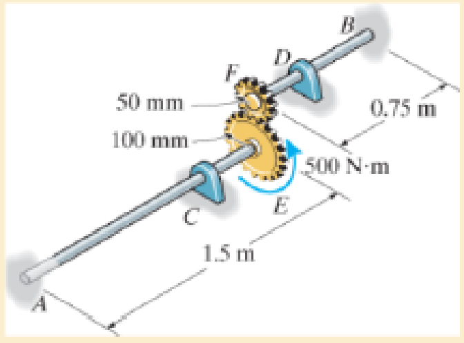
Chapter 5.5, Problem 86P
Each has a diameter of 25 mm and they are connected using the gears fixed to their ends. Their other ends are attached to fixed supports at A and B. They are also supported by journal bearings at C and D, which allow free rotation of the shafts along their axes. If a torque of 500 N · m is applied to the gear at E, determine the reactions at A and B.
Expert Solution & Answer
Want to see the full answer?
Check out a sample textbook solution
Students have asked these similar questions
Q.3 The solid steel shaft has a diameter of 20 mm. If it is subjected to the two torques, determine the
reactions at the fixed supports A and B.
500 N-m
D
0.3 m
800 N-m
1.5 m
0.2 m
The tapered shaft is confined by the fixed supports at A and B. If a torque T is applied at its mid-point, determine the reactions at the supports.
The shaft of radius c is subjected to a distributed torque t, measured as torque>length of shaft. Determine the reactions at the fixed supports A and B.
Chapter 5 Solutions
Mechanics of Materials
Ch. 5.3 - The solid circular shaft is subjected to an...Ch. 5.3 - The hollow circular shaft is subjected to an...Ch. 5.3 - The shaft is hollow from A to B and solid from B...Ch. 5.3 - Determine the maximum shear stress in the...Ch. 5.3 - Determine the maximum shear stress in the shaft at...Ch. 5.3 - Determine the shear stress a: point A on the...Ch. 5.3 - The solid 50-mm-diameter shaft is subjected to the...Ch. 5.3 - The gear motor can develop 3 hp when it turns at...Ch. 5.3 - The solid shaft of radius r is subjected to a...Ch. 5.3 - The solid shaft of radius r is subjected to a...
Ch. 5.3 - Prob. 3PCh. 5.3 - The copper pipe has an outer diameter of 40 mm and...Ch. 5.3 - The copper pipe has an outer diameter of 2.50 in....Ch. 5.3 - The link acts as part of the elevator control for...Ch. 5.3 - The assembly consists of two sections of...Ch. 5.3 - A steel tube having an outer diameter of 2.5 in....Ch. 5.3 - The rod has a diameter of 1 in. and a weight of 10...Ch. 5.3 - The rod has a diameter of 1 in. and a weight of 15...Ch. 5.3 - Prob. 20PCh. 5.3 - The 60-mm-diameter solid shaft is subjected to the...Ch. 5.3 - The 60-mm-diameter solid shaft is subjected to the...Ch. 5.3 - The solid shaft is subjected to the distributed...Ch. 5.3 - If the tube is made from a material having an...Ch. 5.3 - Prob. 29PCh. 5.3 - The motor delivers 50 hp while turning at a...Ch. 5.3 - The solid steel shaft AC has a diameter of 25 mm...Ch. 5.3 - Prob. 35PCh. 5.4 - The 60 mm-diameter steel shaft is subjected to the...Ch. 5.4 - Prob. 10FPCh. 5.4 - The hollow 6061-T6 aluminum shaft has an outer and...Ch. 5.4 - A series of gears are mounted on the...Ch. 5.4 - The 80-mm-diameter shaft is made of steel. If it...Ch. 5.4 - The 80-mm-diameter shaft is made of steel. If it...Ch. 5.4 - The propellers of a ship are connected to an A-36...Ch. 5.4 - Show that the maximum shear strain in the shaft is...Ch. 5.4 - Determine the angle of twist of end B with respect...Ch. 5.4 - Determine the maximum allowable torque T. Also,...Ch. 5.4 - If the allowable shear stress is allow = 80 MPa,...Ch. 5.4 - Determine the angle of twist of the end A.Ch. 5.4 - The hydrofoil boat has an A992 steel propeller...Ch. 5.4 - Also, calculate the absolute maximum shear stress...Ch. 5.4 - If a torque of T = 50 N m is applied to the bolt...Ch. 5.4 - If a torque of T= 50N m is applied to the bolt...Ch. 5.4 - If the motor delivers 4 MW of power to the shaft...Ch. 5.4 - Determine the angle of twist at the free end A of...Ch. 5.5 - Gst = 75 GPa.Ch. 5.5 - The shaft is made of L2 tool steel, has a diameter...Ch. 5.5 - Each has a diameter of 25 mm and they are...Ch. 5.5 - Each has a diameter of 25 mm and they are...Ch. 5.5 - It is fixed at its ends and subjected to a torque...Ch. 5.5 - 5–89. Determine the absolute maximum shear stress...Ch. 5.7 - If the yield stress for brass is Y = 205 MPa,...Ch. 5.7 - By what percentage is the shaft of circular cross...Ch. 5.7 - Prob. 97PCh. 5.7 - Also, find the angle of twist of end B. The shaft...Ch. 5.7 - Also, find the corresponding angle of twist at end...Ch. 5.7 - Prob. 110PCh. 5.7 - Determine the average shear stress in the tube if...Ch. 5.7 - By what percentage is the torsional strength...Ch. 5.7 - Prob. 114PCh. 5.7 - Prob. 115PCh. 5.7 - Prob. 119PCh. 5.10 - Prob. 121PCh. 5.10 - If the radius of the fillet weld connecting the...Ch. 5.10 - Prob. 125PCh. 5.10 - Determine the radius of the elastic core produced...Ch. 5.10 - Prob. 128PCh. 5.10 - Determine the torque T needed to form an elastic...Ch. 5.10 - Determine the torque applied to the shaft.Ch. 5.10 - Prob. 131PCh. 5.10 - Determine the ratio of the plastic torque Tp to...Ch. 5.10 - Determine the applied torque T, which subjects the...Ch. 5.10 - Determine the radius of its elastic core if it is...Ch. 5.10 - Plot the shear-stress distribution acting along a...Ch. 5.10 - If the material obeys a shear stress-strain...Ch. 5.10 - It is made of an elastic perfectly plastic...Ch. 5.10 - Prob. 139PCh. 5.10 - Prob. 140PCh. 5.10 - Prob. 142PCh. 5.10 - Prob. 143PCh. 5 - The shaft is made of A992 steel and has an...Ch. 5 - The shaft is made of A992 steel and has an...Ch. 5 - Determine the shear stress at the mean radius p =...Ch. 5 - If the thickness of its 2014-T6-aluminum skin is...Ch. 5 - Determine which shaft geometry will resist the...Ch. 5 - If couple forces P = 3 kip are applied to the...Ch. 5 - If the allowable shear stress for the aluminum is...Ch. 5 - Determine the angle of twist of its end A if it is...Ch. 5 - This motion is caused by the unequal belt tensions...
Knowledge Booster


Learn more about
Need a deep-dive on the concept behind this application? Look no further. Learn more about this topic, mechanical-engineering and related others by exploring similar questions and additional content below.Similar questions
- Two transmission belts pass over a double-sheaved pulley that is attached to an axle supported by bearings at A and D. The radius of the inner sheave is 125 mm and the radius of the outer sheave is 250 mm. Assuming that the pulley rotates at a constant rate and Tax 112 N. Tg'=84 N, and TC-175 N, determine the reactions at A and D. Assume that the bearing at D does not exert any axial thrust 150 mm The reaction at A is ( The reaction at Dis ( 100 mm B 200 mm Ny+ Nj+ NK Nk. Te Toarrow_forwardThe two shafts are made of A-36 steel. Each has a diameter of 25 mm and they are connected using the gears fixed to their ends. Their other ends are attached to fixed supports at A and B. They are also supported by journalbearings at C and D, which allow free rotation of the shafts along their axes. If a torque of 500 N # m is applied to the gear at E, determine the rotation of this gear.arrow_forwardThe two solid steel shafts are connected by gears C and F and 9 in. 2,5 in. supported by smooth bearings at B, D, and E. The upper shaft is fixed at G. If the shear modulus is G = 11 x 10° ksi, determine the angle of rotation of end A when the torque of 700 lb - ft is аpplied. E 1.75 in. -3 in. 4 ft B 700 lb ft 5 ftarrow_forward
- The steel shaft is fixed at its two ends A and B. If it is subjected to two external torques (1000 N·m and 300 N·m at point C and D, respectively) as shown in the figure, determine the support reactions at two ends A and B.arrow_forwardDetermine the internal torque at each section and show the shear stress on differential volume elements located at A, B, C, and D.arrow_forwardThe shaft has an outer diameter of 100 mm and an inner diameter of 80 mm. If it is subjected to the three torques, plot the shear stress distribution along a radial line for the cross section within region CD of the shaft. The smooth bearings at A and B do not resist torque.arrow_forward
- The cylinder have equal diameter. Solve for the reactions at A, D and C.arrow_forwardThe device shown is used to mix soils in order to provide in-situ stabilization. If the mixer is connected to an A-36 steel tubular shaft that has an inner diameter of 3 in. and an outer diameter of 4.5 in., determine the angle oftwist of the shaft at A relative to C if each mixing blade is subjected to the torques shown.arrow_forwardThe structure is comprised of rigid bars AB and BCD supported by hinges at A and D. A steel rod at C provides additional support to the system. As shown, there is a roller connection between the bars at B. Determine the magnitude of the force P applied as shown if the vertical displacement of point B is limited to 1.5 mm. Neglect the weights of the bars. ( E = 200 GPa A = 300 mm2 L= 3 m A 2 m 2 m C D 1.5 m 3.0 marrow_forward
- The 20-mm-diameter A-36 steel rod is subjected to the axial forces shown. Determine the displacement of end C with respect to the fixed support at A.arrow_forwardThe two shafts are made of A-36 steel. Each has a diameter of 25 mm, and they are supported by bearings at A, B, and C, which allow free rotation. If the support at D is fixed, determine the angle of twist of end A when the torques are applied to the assembly as shown. D 250 mm 120 N-m 60 N-m 200 mm 750 mm 250 mm 100 mnt 300 mm -150 mm B Ans. A=2.09°arrow_forwardis part of a drive 6-101 The shaft shown in Fig. system in a factory. Friction between the belts and pulleys prevents slipping of the belts. Determine the torque T re- quired for equilibrium and the reactions at supports A and B. The support at A is a journal bearing, and the support at B is a thrust bearing. The bearings exert only force reac- tions on the shaft. 6 in. 50 lb 200 lb 150 lb 6 in. 50 lb B 8 in. 14 in. 14 in.arrow_forward
arrow_back_ios
SEE MORE QUESTIONS
arrow_forward_ios
Recommended textbooks for you
 Elements Of ElectromagneticsMechanical EngineeringISBN:9780190698614Author:Sadiku, Matthew N. O.Publisher:Oxford University Press
 Mechanics of Materials (10th Edition)Mechanical EngineeringISBN:9780134319650Author:Russell C. HibbelerPublisher:PEARSON
 Thermodynamics: An Engineering ApproachMechanical EngineeringISBN:9781259822674Author:Yunus A. Cengel Dr., Michael A. BolesPublisher:McGraw-Hill Education
 Control Systems EngineeringMechanical EngineeringISBN:9781118170519Author:Norman S. NisePublisher:WILEY
 Mechanics of Materials (MindTap Course List)Mechanical EngineeringISBN:9781337093347Author:Barry J. Goodno, James M. GerePublisher:Cengage Learning
 Engineering Mechanics: StaticsMechanical EngineeringISBN:9781118807330Author:James L. Meriam, L. G. Kraige, J. N. BoltonPublisher:WILEY
Elements Of Electromagnetics
Mechanical Engineering
ISBN:9780190698614
Author:Sadiku, Matthew N. O.
Publisher:Oxford University Press
Mechanics of Materials (10th Edition)
Mechanical Engineering
ISBN:9780134319650
Author:Russell C. Hibbeler
Publisher:PEARSON
Thermodynamics: An Engineering Approach
Mechanical Engineering
ISBN:9781259822674
Author:Yunus A. Cengel Dr., Michael A. Boles
Publisher:McGraw-Hill Education
Control Systems Engineering
Mechanical Engineering
ISBN:9781118170519
Author:Norman S. Nise
Publisher:WILEY
Mechanics of Materials (MindTap Course List)
Mechanical Engineering
ISBN:9781337093347
Author:Barry J. Goodno, James M. Gere
Publisher:Cengage Learning
Engineering Mechanics: Statics
Mechanical Engineering
ISBN:9781118807330
Author:James L. Meriam, L. G. Kraige, J. N. Bolton
Publisher:WILEY
EVERYTHING on Axial Loading Normal Stress in 10 MINUTES - Mechanics of Materials; Author: Less Boring Lectures;https://www.youtube.com/watch?v=jQ-fNqZWrNg;License: Standard YouTube License, CC-BY