
Mechanics of Materials
11th Edition
ISBN: 9780137605460
Author: Russell C. Hibbeler
Publisher: Pearson Education (US)
expand_more
expand_more
format_list_bulleted
Concept explainers
Videos
Textbook Question
Chapter 5.4, Problem 14FP
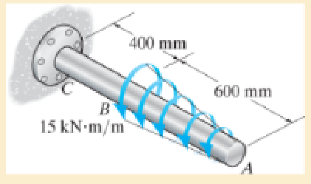
The 80-mm-diameter shaft is made of steel. If it is subjected to the triangular distributed load, determine the angle of twist of end A. Take G = 75 GPa.
Expert Solution & Answer
Want to see the full answer?
Check out a sample textbook solution
Students have asked these similar questions
The 80-mm-diameter shaft is made of steel. If it is subjected to the triangular distributed load, determine the angle of twist of end A. Take G = 75 GPa.
A shaft with two segments (one with constant cross-section of 40-mm-diameter, 500-mm--length and one with the tapered cross-section from 40-mm-diameter to 20-mm-diameter, 400-mm-length) is fixed between walls and a torque T is applied at the junction. Determine the angle of twist at B. Shaft is made of 6061-T6 Aluminum.
The aluminum shaft, composed of three segments, is fastened to rigid supports at A and D. Calculate the maximum shear stress in each segment when the two torques are applied
Chapter 5 Solutions
Mechanics of Materials
Ch. 5.3 - The solid circular shaft is subjected to an...Ch. 5.3 - The hollow circular shaft is subjected to an...Ch. 5.3 - The shaft is hollow from A to B and solid from B...Ch. 5.3 - Determine the maximum shear stress in the...Ch. 5.3 - Determine the maximum shear stress in the shaft at...Ch. 5.3 - Determine the shear stress a: point A on the...Ch. 5.3 - The solid 50-mm-diameter shaft is subjected to the...Ch. 5.3 - The gear motor can develop 3 hp when it turns at...Ch. 5.3 - The solid shaft of radius r is subjected to a...Ch. 5.3 - The solid shaft of radius r is subjected to a...
Ch. 5.3 - Prob. 3PCh. 5.3 - The copper pipe has an outer diameter of 40 mm and...Ch. 5.3 - The copper pipe has an outer diameter of 2.50 in....Ch. 5.3 - The link acts as part of the elevator control for...Ch. 5.3 - The assembly consists of two sections of...Ch. 5.3 - A steel tube having an outer diameter of 2.5 in....Ch. 5.3 - The rod has a diameter of 1 in. and a weight of 10...Ch. 5.3 - The rod has a diameter of 1 in. and a weight of 15...Ch. 5.3 - Prob. 20PCh. 5.3 - The 60-mm-diameter solid shaft is subjected to the...Ch. 5.3 - The 60-mm-diameter solid shaft is subjected to the...Ch. 5.3 - The solid shaft is subjected to the distributed...Ch. 5.3 - If the tube is made from a material having an...Ch. 5.3 - Prob. 29PCh. 5.3 - The motor delivers 50 hp while turning at a...Ch. 5.3 - The solid steel shaft AC has a diameter of 25 mm...Ch. 5.3 - Prob. 35PCh. 5.4 - The 60 mm-diameter steel shaft is subjected to the...Ch. 5.4 - Prob. 10FPCh. 5.4 - The hollow 6061-T6 aluminum shaft has an outer and...Ch. 5.4 - A series of gears are mounted on the...Ch. 5.4 - The 80-mm-diameter shaft is made of steel. If it...Ch. 5.4 - The 80-mm-diameter shaft is made of steel. If it...Ch. 5.4 - The propellers of a ship are connected to an A-36...Ch. 5.4 - Show that the maximum shear strain in the shaft is...Ch. 5.4 - Determine the angle of twist of end B with respect...Ch. 5.4 - Determine the maximum allowable torque T. Also,...Ch. 5.4 - If the allowable shear stress is allow = 80 MPa,...Ch. 5.4 - Determine the angle of twist of the end A.Ch. 5.4 - The hydrofoil boat has an A992 steel propeller...Ch. 5.4 - Also, calculate the absolute maximum shear stress...Ch. 5.4 - If a torque of T = 50 N m is applied to the bolt...Ch. 5.4 - If a torque of T= 50N m is applied to the bolt...Ch. 5.4 - If the motor delivers 4 MW of power to the shaft...Ch. 5.4 - Determine the angle of twist at the free end A of...Ch. 5.5 - Gst = 75 GPa.Ch. 5.5 - The shaft is made of L2 tool steel, has a diameter...Ch. 5.5 - Each has a diameter of 25 mm and they are...Ch. 5.5 - Each has a diameter of 25 mm and they are...Ch. 5.5 - It is fixed at its ends and subjected to a torque...Ch. 5.5 - 5–89. Determine the absolute maximum shear stress...Ch. 5.7 - If the yield stress for brass is Y = 205 MPa,...Ch. 5.7 - By what percentage is the shaft of circular cross...Ch. 5.7 - Prob. 97PCh. 5.7 - Also, find the angle of twist of end B. The shaft...Ch. 5.7 - Also, find the corresponding angle of twist at end...Ch. 5.7 - Prob. 110PCh. 5.7 - Determine the average shear stress in the tube if...Ch. 5.7 - By what percentage is the torsional strength...Ch. 5.7 - Prob. 114PCh. 5.7 - Prob. 115PCh. 5.7 - Prob. 119PCh. 5.10 - Prob. 121PCh. 5.10 - If the radius of the fillet weld connecting the...Ch. 5.10 - Prob. 125PCh. 5.10 - Determine the radius of the elastic core produced...Ch. 5.10 - Prob. 128PCh. 5.10 - Determine the torque T needed to form an elastic...Ch. 5.10 - Determine the torque applied to the shaft.Ch. 5.10 - Prob. 131PCh. 5.10 - Determine the ratio of the plastic torque Tp to...Ch. 5.10 - Determine the applied torque T, which subjects the...Ch. 5.10 - Determine the radius of its elastic core if it is...Ch. 5.10 - Plot the shear-stress distribution acting along a...Ch. 5.10 - If the material obeys a shear stress-strain...Ch. 5.10 - It is made of an elastic perfectly plastic...Ch. 5.10 - Prob. 139PCh. 5.10 - Prob. 140PCh. 5.10 - Prob. 142PCh. 5.10 - Prob. 143PCh. 5 - The shaft is made of A992 steel and has an...Ch. 5 - The shaft is made of A992 steel and has an...Ch. 5 - Determine the shear stress at the mean radius p =...Ch. 5 - If the thickness of its 2014-T6-aluminum skin is...Ch. 5 - Determine which shaft geometry will resist the...Ch. 5 - If couple forces P = 3 kip are applied to the...Ch. 5 - If the allowable shear stress for the aluminum is...Ch. 5 - Determine the angle of twist of its end A if it is...Ch. 5 - This motion is caused by the unequal belt tensions...
Knowledge Booster


Learn more about
Need a deep-dive on the concept behind this application? Look no further. Learn more about this topic, mechanical-engineering and related others by exploring similar questions and additional content below.Similar questions
- The motor produces a torque of T = 20 N # m on gear A. If gear C is suddenly locked so it does not turn, yet B can freely turn, determine the angle of twist of F with respect to E and F with respect to D of the L2-steel shaft, which hasan inner diameter of 30 mm and an outer diameter of 50 mm. Also, calculate the absolute maximum shear stress in the shaft. The shaft is supported on journal bearings at G at H.arrow_forwardThe shaft is made from a solid steel section AB and a tubular portion made of steel and having a brass core. If it is fixed to a rigid support at A, and a torque of T = 50 lb.ft is applied to it at C, determine the rotation angle that occurs at C relative to A and compute the maximum shear stress and maximum shear strain in the brass and steel. Take Gst = 11500 ksi, Gbr = 5600 Ksi. 3 ft 0.5 in. B 1 in. T = 50 lb•ftarrow_forwardIf the solid shaft AB to which the valve handle is attached is made of C83400 red brass and has a diameter of 10 mm, determine the maximum couple forces F that can be applied to the handle just before the material starts to fail. Take 7allow = 40 MPa. What is the angle of twist of the handle? The shaft is fixed at A. 150 mm 150 mm 150 mmarrow_forward
- The tapered shaft has a length L and a radius r at end A and 2r at end B. If it is fixed at end B and is subjected to a torque T, determine the angle of twist of end A. the shear modulus is G.arrow_forwardTwo solid steel shafts of different diameters are joined together at point C. The diameter of the smaller shaft is 0.5 inch, while the diameter of the larger shaft is 1 inch. If the supports at both ends, A & B, are unyielding / rigid, and a counterclockwise torque of 500 ft lb is applied at point D, determine the maximum shear stress in the shaft in ksi. The modulus of rigidity for steel is 10800 ksi. 8 in 5 in 12 inarrow_forwardtwo solid steel shafts of different diameters are joined together at point C. the diameter of the smaller shaft is 0.5 in, while the diameter of the larger shaft is 1 in. if the supports at both ends, A & B, are unyielding / rigid, and a counterclockwise torque of 500 ft lb at point D, determine the maximum shear stress in the shaft in ksi. The modulus of rigidity for steel is 10800 ksi.Show full solution pleasearrow_forward
- Two forces, each of magnitude P, are applied to the wrench. The diameter of the steel shaft AB is 30mm. Determine the largest allowable value of P if the shear stress in the shaft is not to exceed 120MPa and it's angle of twist is limited to 7deg. Use G=83GPa for steel. -Draw and label the diagram correctly, No diagram in the solution will be marked wrong. -Shortcut solution will be marked wrong.arrow_forwardIf end B of the shaft, which has an equilateral triangular cross-section, is subjected to a torque of T = 900 lb # ft, determine the maximum shear stress in the shaft. Also, find the angle of twist of end B. The shaft is made from 6061-T1 aluminum.arrow_forwardThe device shown is used to mix soils in order to provide in-situ stabilization. If the mixer is connected to an A-36 steel tubular shaft that has an inner diameter of 3 in. and an outer diameter of 4.5 in, determine the angle of twistof the shaft at A relative to B and the absolute maximum shear stress in the shaft if each mixing blade is subjected to the torques shown.arrow_forward
- The 80-mm-diameter shaft is made of steel. If it is subjected to the uniform distributed torque, determine the angle of twist of end A. Take G = 75 GPa. 800 mm 5 kN m/m Aarrow_forwardThe two shafts are made of A-36 steel (shear modulus G = 75 MPa). Each has a diameter of 25 mm, and they are supported by bearings at A, B, and C, which allow free rotation. If the support at D is fixed, determine a.) the angle of twist of end A and b.) the maximum torsional stress in the shaft, when the two torques of 60 N-m are applied to the assembly as shown, one on shaft ABand the other on shaft CD .arrow_forwardThe two solid steel shafts are connected by gears C and F and 9 in. 2,5 in. supported by smooth bearings at B, D, and E. The upper shaft is fixed at G. If the shear modulus is G = 11 x 10° ksi, determine the angle of rotation of end A when the torque of 700 lb - ft is аpplied. E 1.75 in. -3 in. 4 ft B 700 lb ft 5 ftarrow_forward
arrow_back_ios
SEE MORE QUESTIONS
arrow_forward_ios
Recommended textbooks for you
 Elements Of ElectromagneticsMechanical EngineeringISBN:9780190698614Author:Sadiku, Matthew N. O.Publisher:Oxford University Press
 Mechanics of Materials (10th Edition)Mechanical EngineeringISBN:9780134319650Author:Russell C. HibbelerPublisher:PEARSON
 Thermodynamics: An Engineering ApproachMechanical EngineeringISBN:9781259822674Author:Yunus A. Cengel Dr., Michael A. BolesPublisher:McGraw-Hill Education
 Control Systems EngineeringMechanical EngineeringISBN:9781118170519Author:Norman S. NisePublisher:WILEY
 Mechanics of Materials (MindTap Course List)Mechanical EngineeringISBN:9781337093347Author:Barry J. Goodno, James M. GerePublisher:Cengage Learning
 Engineering Mechanics: StaticsMechanical EngineeringISBN:9781118807330Author:James L. Meriam, L. G. Kraige, J. N. BoltonPublisher:WILEY
Elements Of Electromagnetics
Mechanical Engineering
ISBN:9780190698614
Author:Sadiku, Matthew N. O.
Publisher:Oxford University Press
Mechanics of Materials (10th Edition)
Mechanical Engineering
ISBN:9780134319650
Author:Russell C. Hibbeler
Publisher:PEARSON
Thermodynamics: An Engineering Approach
Mechanical Engineering
ISBN:9781259822674
Author:Yunus A. Cengel Dr., Michael A. Boles
Publisher:McGraw-Hill Education
Control Systems Engineering
Mechanical Engineering
ISBN:9781118170519
Author:Norman S. Nise
Publisher:WILEY
Mechanics of Materials (MindTap Course List)
Mechanical Engineering
ISBN:9781337093347
Author:Barry J. Goodno, James M. Gere
Publisher:Cengage Learning
Engineering Mechanics: Statics
Mechanical Engineering
ISBN:9781118807330
Author:James L. Meriam, L. G. Kraige, J. N. Bolton
Publisher:WILEY
Understanding Torsion; Author: The Efficient Engineer;https://www.youtube.com/watch?v=1YTKedLQOa0;License: Standard YouTube License, CC-BY