
Mechanics of Materials
11th Edition
ISBN: 9780137605460
Author: Russell C. Hibbeler
Publisher: Pearson Education (US)
expand_more
expand_more
format_list_bulleted
Concept explainers
Videos
Textbook Question
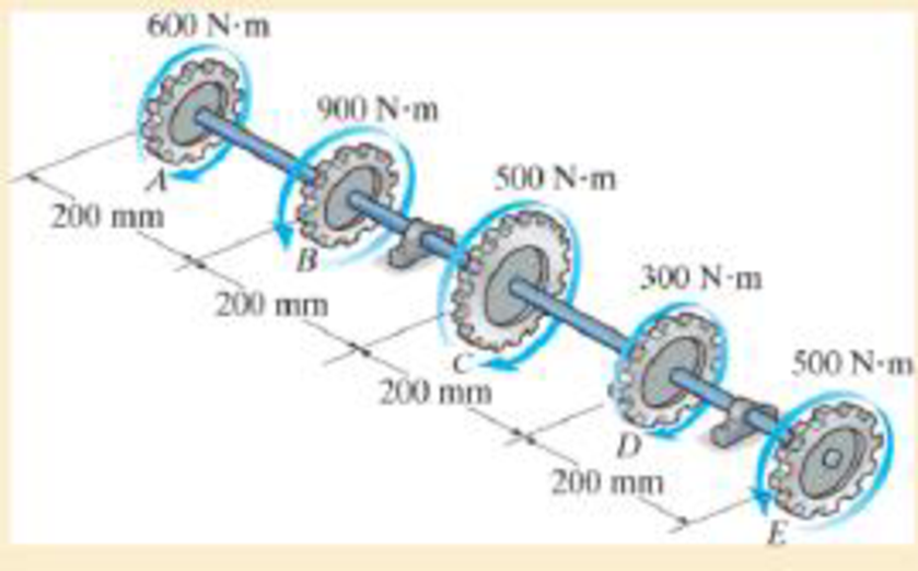
Chapter 5.4, Problem 12FP
A series of gears are mounted on the 40-mm-diameter steel shaft. Determine the angle of twist of gear E relative to gear A. Take G = 75 GPa.
Expert Solution & Answer
Want to see the full answer?
Check out a sample textbook solution
Students have asked these similar questions
An aluminum shaft with a constant diameter of 70 mm is loaded by torques
applied to gears attached to it. Use G = 28 GPa,
Determine the relative angle of twist of gear D relative to gear A (in
degrees).
What is the direction of the rotation of A relative to D?
PROBLEM 1. The shafts are made of A-36 steel and both have 100 mm diameter. If a torque of 60
kN.m is applied to end E and 25 kN.m to the D gear as shown in the figure, determine the angle of
twist of the section at E of the DE shaft.
0.75 m
0.75 m
A
B
150 mm
25 kN-m
300 mm
60 kN.m
1.25 m
E
PROBLEM 1. The shafts are made of A-36 steel and both have 100 mm diameter. If a torque of 60
kN.m is applied to end E and 25 kN.m to the D gear as shown in the figure, determine the angle of
twist of the section at E of the DE shaft.
0.75 m
0.75 m
150 mm
25 kN-m
300 mm
60 kN.m
1.25 m
E
Chapter 5 Solutions
Mechanics of Materials
Ch. 5.3 - The solid circular shaft is subjected to an...Ch. 5.3 - The hollow circular shaft is subjected to an...Ch. 5.3 - The shaft is hollow from A to B and solid from B...Ch. 5.3 - Determine the maximum shear stress in the...Ch. 5.3 - Determine the maximum shear stress in the shaft at...Ch. 5.3 - Determine the shear stress a: point A on the...Ch. 5.3 - The solid 50-mm-diameter shaft is subjected to the...Ch. 5.3 - The gear motor can develop 3 hp when it turns at...Ch. 5.3 - The solid shaft of radius r is subjected to a...Ch. 5.3 - The solid shaft of radius r is subjected to a...
Ch. 5.3 - Prob. 3PCh. 5.3 - The copper pipe has an outer diameter of 40 mm and...Ch. 5.3 - The copper pipe has an outer diameter of 2.50 in....Ch. 5.3 - The link acts as part of the elevator control for...Ch. 5.3 - The assembly consists of two sections of...Ch. 5.3 - A steel tube having an outer diameter of 2.5 in....Ch. 5.3 - The rod has a diameter of 1 in. and a weight of 10...Ch. 5.3 - The rod has a diameter of 1 in. and a weight of 15...Ch. 5.3 - Prob. 20PCh. 5.3 - The 60-mm-diameter solid shaft is subjected to the...Ch. 5.3 - The 60-mm-diameter solid shaft is subjected to the...Ch. 5.3 - The solid shaft is subjected to the distributed...Ch. 5.3 - If the tube is made from a material having an...Ch. 5.3 - Prob. 29PCh. 5.3 - The motor delivers 50 hp while turning at a...Ch. 5.3 - The solid steel shaft AC has a diameter of 25 mm...Ch. 5.3 - Prob. 35PCh. 5.4 - The 60 mm-diameter steel shaft is subjected to the...Ch. 5.4 - Prob. 10FPCh. 5.4 - The hollow 6061-T6 aluminum shaft has an outer and...Ch. 5.4 - A series of gears are mounted on the...Ch. 5.4 - The 80-mm-diameter shaft is made of steel. If it...Ch. 5.4 - The 80-mm-diameter shaft is made of steel. If it...Ch. 5.4 - The propellers of a ship are connected to an A-36...Ch. 5.4 - Show that the maximum shear strain in the shaft is...Ch. 5.4 - Determine the angle of twist of end B with respect...Ch. 5.4 - Determine the maximum allowable torque T. Also,...Ch. 5.4 - If the allowable shear stress is allow = 80 MPa,...Ch. 5.4 - Determine the angle of twist of the end A.Ch. 5.4 - The hydrofoil boat has an A992 steel propeller...Ch. 5.4 - Also, calculate the absolute maximum shear stress...Ch. 5.4 - If a torque of T = 50 N m is applied to the bolt...Ch. 5.4 - If a torque of T= 50N m is applied to the bolt...Ch. 5.4 - If the motor delivers 4 MW of power to the shaft...Ch. 5.4 - Determine the angle of twist at the free end A of...Ch. 5.5 - Gst = 75 GPa.Ch. 5.5 - The shaft is made of L2 tool steel, has a diameter...Ch. 5.5 - Each has a diameter of 25 mm and they are...Ch. 5.5 - Each has a diameter of 25 mm and they are...Ch. 5.5 - It is fixed at its ends and subjected to a torque...Ch. 5.5 - 5–89. Determine the absolute maximum shear stress...Ch. 5.7 - If the yield stress for brass is Y = 205 MPa,...Ch. 5.7 - By what percentage is the shaft of circular cross...Ch. 5.7 - Prob. 97PCh. 5.7 - Also, find the angle of twist of end B. The shaft...Ch. 5.7 - Also, find the corresponding angle of twist at end...Ch. 5.7 - Prob. 110PCh. 5.7 - Determine the average shear stress in the tube if...Ch. 5.7 - By what percentage is the torsional strength...Ch. 5.7 - Prob. 114PCh. 5.7 - Prob. 115PCh. 5.7 - Prob. 119PCh. 5.10 - Prob. 121PCh. 5.10 - If the radius of the fillet weld connecting the...Ch. 5.10 - Prob. 125PCh. 5.10 - Determine the radius of the elastic core produced...Ch. 5.10 - Prob. 128PCh. 5.10 - Determine the torque T needed to form an elastic...Ch. 5.10 - Determine the torque applied to the shaft.Ch. 5.10 - Prob. 131PCh. 5.10 - Determine the ratio of the plastic torque Tp to...Ch. 5.10 - Determine the applied torque T, which subjects the...Ch. 5.10 - Determine the radius of its elastic core if it is...Ch. 5.10 - Plot the shear-stress distribution acting along a...Ch. 5.10 - If the material obeys a shear stress-strain...Ch. 5.10 - It is made of an elastic perfectly plastic...Ch. 5.10 - Prob. 139PCh. 5.10 - Prob. 140PCh. 5.10 - Prob. 142PCh. 5.10 - Prob. 143PCh. 5 - The shaft is made of A992 steel and has an...Ch. 5 - The shaft is made of A992 steel and has an...Ch. 5 - Determine the shear stress at the mean radius p =...Ch. 5 - If the thickness of its 2014-T6-aluminum skin is...Ch. 5 - Determine which shaft geometry will resist the...Ch. 5 - If couple forces P = 3 kip are applied to the...Ch. 5 - If the allowable shear stress for the aluminum is...Ch. 5 - Determine the angle of twist of its end A if it is...Ch. 5 - This motion is caused by the unequal belt tensions...
Knowledge Booster


Learn more about
Need a deep-dive on the concept behind this application? Look no further. Learn more about this topic, mechanical-engineering and related others by exploring similar questions and additional content below.Similar questions
- A 1. The splined ends and gears attached to the A-36 steel shaft are subjected to the torques shown. Determine the angle of twist of end B with respect to end A. The shaft has a diameter of 40 300 N·m 300 mm 500 N-m 400 mm 200 N-m 500 mm 400 N-marrow_forwardAn aluminum shaft with a constant diameter of 50mm is loaded by torques applied to gears shown. Using G=28GPa, determine the angle of twist of gear D relative to gear A.arrow_forwardThe shafts are made of steel with shear modulus of 75 GPa. Determine the angle of twist of gear B if a torque of 30 kN·m is applied to gear B. Both shafts have the same diameter of 90 mm. (Hint: for the meshing cylindrical gears, i.e. gear C and D, the angle of twist need to time the radius of the gear while applying the equation of compatibility.)arrow_forward
- 1. The 40-mm-diameter steel shaft is subjected to the torques shown. Determine the angle of twist of end B with respect to A. Use the sign convention for internal torques and take G= 75GPa. FBDs of cut sections OR an internal torque diagram is required for full credit. 80 N-m 20 N-m 30 N-m 600 mm 800 mm 200 mmarrow_forwardThe four rigid gears, loaded as shown in Fig. (a), are attached to a 2-in.-diameter steel shaft. Compute the angle θ of rotation of gearA relative to gear D. Use G= 12×106 psi for the shaftarrow_forward2. The solid 50-mm-diameter shaft is used to transmit the torques applied to the gears. Determine the absolute maximum shear stress in the shaft. (Source: R.C. Hibbeler) 250 N-m 75 N-m 325 N-m B 150 N-m 300 mm C 400 mm 500 mmarrow_forward
- The 63-mm diameter shaft is subjected to the torques as shown. Determine the angle of twist (in degree) of end A with respect to C. G= 33 GPa C 400 mm B 3 kN-m 600 mm 2 kN-m Do not include units in final answer. Answer in 3 decimal places.arrow_forwardTORSION An aluminum shaft with a constant diameter of 70 mm is loaded by torques applied to gears attached to it. Use G = 28 GPa. DETERMINE: A. the relative angle of twist of gear D relative to gear A (in degrees) B. the direction of the rotation of A relative to D? PROVIDE FBDarrow_forwardDetermine the gear forces if Gear 1 is rotating at 600 rpm and transmitting 250 kW power. The module of the gears is m=2,5 mm and the pressure angle – a = 20°.arrow_forward
- The ends and gears connected to the steel shaft (G = 75 GPa) aresubject to the torques shown. Determine the torsional angle of end B with respect to A.The shaft has a diameter of 40 mm.arrow_forwardThe gears attached to the A-36 steel shaft are subjected to the torques shown. Determine the angle of twist of end C with respect to end A. The shaft has a diameter of 40 mm. A 0.2 m AAN 300 N·m B 0.5 m GRAA 100 N·m C 200 N·marrow_forwardThe 54-mm diameter shaft is subjected to the torques as shown. Determine the angle of twist (in degree) of end A with respect to C. G= 36 GPa 400 mm B 3 kN-m 600 mm 2 kN-m Do not include units in final answer. Answer in 3 decimal places.arrow_forward
arrow_back_ios
SEE MORE QUESTIONS
arrow_forward_ios
Recommended textbooks for you
 Elements Of ElectromagneticsMechanical EngineeringISBN:9780190698614Author:Sadiku, Matthew N. O.Publisher:Oxford University Press
 Mechanics of Materials (10th Edition)Mechanical EngineeringISBN:9780134319650Author:Russell C. HibbelerPublisher:PEARSON
 Thermodynamics: An Engineering ApproachMechanical EngineeringISBN:9781259822674Author:Yunus A. Cengel Dr., Michael A. BolesPublisher:McGraw-Hill Education
 Control Systems EngineeringMechanical EngineeringISBN:9781118170519Author:Norman S. NisePublisher:WILEY
 Mechanics of Materials (MindTap Course List)Mechanical EngineeringISBN:9781337093347Author:Barry J. Goodno, James M. GerePublisher:Cengage Learning
 Engineering Mechanics: StaticsMechanical EngineeringISBN:9781118807330Author:James L. Meriam, L. G. Kraige, J. N. BoltonPublisher:WILEY
Elements Of Electromagnetics
Mechanical Engineering
ISBN:9780190698614
Author:Sadiku, Matthew N. O.
Publisher:Oxford University Press
Mechanics of Materials (10th Edition)
Mechanical Engineering
ISBN:9780134319650
Author:Russell C. Hibbeler
Publisher:PEARSON
Thermodynamics: An Engineering Approach
Mechanical Engineering
ISBN:9781259822674
Author:Yunus A. Cengel Dr., Michael A. Boles
Publisher:McGraw-Hill Education
Control Systems Engineering
Mechanical Engineering
ISBN:9781118170519
Author:Norman S. Nise
Publisher:WILEY
Mechanics of Materials (MindTap Course List)
Mechanical Engineering
ISBN:9781337093347
Author:Barry J. Goodno, James M. Gere
Publisher:Cengage Learning
Engineering Mechanics: Statics
Mechanical Engineering
ISBN:9781118807330
Author:James L. Meriam, L. G. Kraige, J. N. Bolton
Publisher:WILEY
Understanding Torsion; Author: The Efficient Engineer;https://www.youtube.com/watch?v=1YTKedLQOa0;License: Standard YouTube License, CC-BY