
Mechanics of Materials
11th Edition
ISBN: 9780137605460
Author: Russell C. Hibbeler
Publisher: Pearson Education (US)
expand_more
expand_more
format_list_bulleted
Concept explainers
Videos
Textbook Question
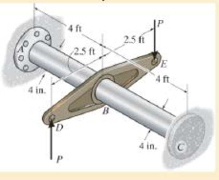
Chapter 5, Problem 7RP
If the allowable shear stress for the aluminum is (τallow)al = 12 ksi and for the steel (τallow)st = 10 ksi, determine the maximum allowable couple forces P that can be applied to the lever arm. The assembly is fixed at A and C.
Expert Solution & Answer
Want to see the full answer?
Check out a sample textbook solution
Students have asked these similar questions
Determine the magnitude of the pin force at A.
Assume W = 900 Ib, a = 5.8 ft, b = 3.9 ft, r = 9 in.
B
W
Answer: A =
i
Ib
The rigid bar AB and CD are supported by pins at A and D. the vertical rods are made of aluminum and bronze. Determine the vertical displacement of the point where the force P= 10 kips is applied. Neglect the weight of the members.
If P = 4.1 kN , determine the horizontal displacement of end F of rod EF.
Chapter 5 Solutions
Mechanics of Materials
Ch. 5.3 - The solid circular shaft is subjected to an...Ch. 5.3 - The hollow circular shaft is subjected to an...Ch. 5.3 - The shaft is hollow from A to B and solid from B...Ch. 5.3 - Determine the maximum shear stress in the...Ch. 5.3 - Determine the maximum shear stress in the shaft at...Ch. 5.3 - Determine the shear stress a: point A on the...Ch. 5.3 - The solid 50-mm-diameter shaft is subjected to the...Ch. 5.3 - The gear motor can develop 3 hp when it turns at...Ch. 5.3 - The solid shaft of radius r is subjected to a...Ch. 5.3 - The solid shaft of radius r is subjected to a...
Ch. 5.3 - Prob. 3PCh. 5.3 - The copper pipe has an outer diameter of 40 mm and...Ch. 5.3 - The copper pipe has an outer diameter of 2.50 in....Ch. 5.3 - The link acts as part of the elevator control for...Ch. 5.3 - The assembly consists of two sections of...Ch. 5.3 - A steel tube having an outer diameter of 2.5 in....Ch. 5.3 - The rod has a diameter of 1 in. and a weight of 10...Ch. 5.3 - The rod has a diameter of 1 in. and a weight of 15...Ch. 5.3 - Prob. 20PCh. 5.3 - The 60-mm-diameter solid shaft is subjected to the...Ch. 5.3 - The 60-mm-diameter solid shaft is subjected to the...Ch. 5.3 - The solid shaft is subjected to the distributed...Ch. 5.3 - If the tube is made from a material having an...Ch. 5.3 - Prob. 29PCh. 5.3 - The motor delivers 50 hp while turning at a...Ch. 5.3 - The solid steel shaft AC has a diameter of 25 mm...Ch. 5.3 - Prob. 35PCh. 5.4 - The 60 mm-diameter steel shaft is subjected to the...Ch. 5.4 - Prob. 10FPCh. 5.4 - The hollow 6061-T6 aluminum shaft has an outer and...Ch. 5.4 - A series of gears are mounted on the...Ch. 5.4 - The 80-mm-diameter shaft is made of steel. If it...Ch. 5.4 - The 80-mm-diameter shaft is made of steel. If it...Ch. 5.4 - The propellers of a ship are connected to an A-36...Ch. 5.4 - Show that the maximum shear strain in the shaft is...Ch. 5.4 - Determine the angle of twist of end B with respect...Ch. 5.4 - Determine the maximum allowable torque T. Also,...Ch. 5.4 - If the allowable shear stress is allow = 80 MPa,...Ch. 5.4 - Determine the angle of twist of the end A.Ch. 5.4 - The hydrofoil boat has an A992 steel propeller...Ch. 5.4 - Also, calculate the absolute maximum shear stress...Ch. 5.4 - If a torque of T = 50 N m is applied to the bolt...Ch. 5.4 - If a torque of T= 50N m is applied to the bolt...Ch. 5.4 - If the motor delivers 4 MW of power to the shaft...Ch. 5.4 - Determine the angle of twist at the free end A of...Ch. 5.5 - Gst = 75 GPa.Ch. 5.5 - The shaft is made of L2 tool steel, has a diameter...Ch. 5.5 - Each has a diameter of 25 mm and they are...Ch. 5.5 - Each has a diameter of 25 mm and they are...Ch. 5.5 - It is fixed at its ends and subjected to a torque...Ch. 5.5 - 5–89. Determine the absolute maximum shear stress...Ch. 5.7 - If the yield stress for brass is Y = 205 MPa,...Ch. 5.7 - By what percentage is the shaft of circular cross...Ch. 5.7 - Prob. 97PCh. 5.7 - Also, find the angle of twist of end B. The shaft...Ch. 5.7 - Also, find the corresponding angle of twist at end...Ch. 5.7 - Prob. 110PCh. 5.7 - Determine the average shear stress in the tube if...Ch. 5.7 - By what percentage is the torsional strength...Ch. 5.7 - Prob. 114PCh. 5.7 - Prob. 115PCh. 5.7 - Prob. 119PCh. 5.10 - Prob. 121PCh. 5.10 - If the radius of the fillet weld connecting the...Ch. 5.10 - Prob. 125PCh. 5.10 - Determine the radius of the elastic core produced...Ch. 5.10 - Prob. 128PCh. 5.10 - Determine the torque T needed to form an elastic...Ch. 5.10 - Determine the torque applied to the shaft.Ch. 5.10 - Prob. 131PCh. 5.10 - Determine the ratio of the plastic torque Tp to...Ch. 5.10 - Determine the applied torque T, which subjects the...Ch. 5.10 - Determine the radius of its elastic core if it is...Ch. 5.10 - Plot the shear-stress distribution acting along a...Ch. 5.10 - If the material obeys a shear stress-strain...Ch. 5.10 - It is made of an elastic perfectly plastic...Ch. 5.10 - Prob. 139PCh. 5.10 - Prob. 140PCh. 5.10 - Prob. 142PCh. 5.10 - Prob. 143PCh. 5 - The shaft is made of A992 steel and has an...Ch. 5 - The shaft is made of A992 steel and has an...Ch. 5 - Determine the shear stress at the mean radius p =...Ch. 5 - If the thickness of its 2014-T6-aluminum skin is...Ch. 5 - Determine which shaft geometry will resist the...Ch. 5 - If couple forces P = 3 kip are applied to the...Ch. 5 - If the allowable shear stress for the aluminum is...Ch. 5 - Determine the angle of twist of its end A if it is...Ch. 5 - This motion is caused by the unequal belt tensions...
Knowledge Booster


Learn more about
Need a deep-dive on the concept behind this application? Look no further. Learn more about this topic, mechanical-engineering and related others by exploring similar questions and additional content below.Similar questions
- Determine the largest internal normal force in the bar.arrow_forwardDetermine the magnitude of the pin force at A. Assume W = 750 lb, a = 2.7 ft, b = 2.0 ft, r = 6 in. a a r B A C W Answer: A = i D lb barrow_forwardThe bronze C86100 pipe has an outer diameter of 1.5 in. and a thickness of 0.125 in. The coupling on it at C is being tightened using a wrench. If the torque developed at A is 125 lb # in., determine the magnitude F of the couple forces. The pipe is fixed supported at end B.arrow_forward
- Determine the internal forces in sections a-a and b-b F1 = 11 KN D2 D2=1.Sm D1 DI=3 m 45° 45° 3 marrow_forwardThe connection is made using a bolt and nut and two washers. If the allowable bearing stress of the washers on the boards is (sb)allow = 2 ksi, and the allowable tensile stress within the bolt shank S is (st)allow = 18 ksi, determine the maximum allowable tension in the bolt shank. The bolt shankhas a diameter of 0.31 in., and the washers have an outer diameter of 0.75 in. and inner diameter (hole) of 0.50 in.arrow_forwardBoth portions of the rod ABC are made of aluminum for which E = 70 GPa. Determine the deformation at segment AB in millimeters if P = 42 kN and Q = 0.arrow_forward
- Determine the magnitude of the pin force at A. Assume W = 810 lb, a = 4.6 ft, b = 3.2 ft, r = 9 in. W C Answer: Ai a B - a A D lb barrow_forwardThe structure is comprised of rigid bars AB and BCD supported by hinges at A and D. A steel rod at C provides additional support to the system. As shown, there is a roller connection between the bars at B. Determine the magnitude of the force P applied as shown if the vertical displacement of point B is limited to 1.5 mm. Neglect the weights of the bars. ( E = 200 GPa A = 300 mm2 L= 3 m A 2 m 2 m C D 1.5 m 3.0 marrow_forwardThe link AB of the pliers has the cross section dimensions 3mm x 20mm, and is made of steel with elastic modulus E= 190 GPa. Determine the value of the force F that would cause failure of the link by bucklingarrow_forward
- Determine the allowable weight that the assembly can handle if the cable AB has a working stress of 200 Mpa and cable AC has a working stress of 150 Mpa. The cable cross sectional areas are 300 mm2for cable AB and 330 mm2for cable AC.arrow_forwardThe two steel shafts (1) and (2) each Ø10 should be connected to each other with the help of the sleeve (3) (Øinner = 10, Øoutside = 15) also made of steel and two rivets at the points shown. The shaft (1) is firmly clamped on the left- hand side, the force F = 100 N acts on shaft 2 in the direction of the arrow. How are the brass round rivets to be dimensioned so that a safety of the coupling against failure of S = 10 is achieved? hole for rivets 1 F 3 a) What type of connection does a riveted connection have? b) What type of load does the rivet have? c) What is the diameter of the rivets? d) Which areas of the rivet are loaded? (Draw in figure and formula) e) Dimension the rivetarrow_forward
arrow_back_ios
arrow_forward_ios
Recommended textbooks for you
 Elements Of ElectromagneticsMechanical EngineeringISBN:9780190698614Author:Sadiku, Matthew N. O.Publisher:Oxford University Press
 Mechanics of Materials (10th Edition)Mechanical EngineeringISBN:9780134319650Author:Russell C. HibbelerPublisher:PEARSON
 Thermodynamics: An Engineering ApproachMechanical EngineeringISBN:9781259822674Author:Yunus A. Cengel Dr., Michael A. BolesPublisher:McGraw-Hill Education
 Control Systems EngineeringMechanical EngineeringISBN:9781118170519Author:Norman S. NisePublisher:WILEY
 Mechanics of Materials (MindTap Course List)Mechanical EngineeringISBN:9781337093347Author:Barry J. Goodno, James M. GerePublisher:Cengage Learning
 Engineering Mechanics: StaticsMechanical EngineeringISBN:9781118807330Author:James L. Meriam, L. G. Kraige, J. N. BoltonPublisher:WILEY
Elements Of Electromagnetics
Mechanical Engineering
ISBN:9780190698614
Author:Sadiku, Matthew N. O.
Publisher:Oxford University Press
Mechanics of Materials (10th Edition)
Mechanical Engineering
ISBN:9780134319650
Author:Russell C. Hibbeler
Publisher:PEARSON
Thermodynamics: An Engineering Approach
Mechanical Engineering
ISBN:9781259822674
Author:Yunus A. Cengel Dr., Michael A. Boles
Publisher:McGraw-Hill Education
Control Systems Engineering
Mechanical Engineering
ISBN:9781118170519
Author:Norman S. Nise
Publisher:WILEY
Mechanics of Materials (MindTap Course List)
Mechanical Engineering
ISBN:9781337093347
Author:Barry J. Goodno, James M. Gere
Publisher:Cengage Learning
Engineering Mechanics: Statics
Mechanical Engineering
ISBN:9781118807330
Author:James L. Meriam, L. G. Kraige, J. N. Bolton
Publisher:WILEY
Everything About COMBINED LOADING in 10 Minutes! Mechanics of Materials; Author: Less Boring Lectures;https://www.youtube.com/watch?v=N-PlI900hSg;License: Standard youtube license