
Concept explainers
Videos
Assuming that the front and rear axle loads remain in the same ratio as for the truck of Prob. 5.96, determine how much heavier a truck could safely cross the bridge designed in that problem.
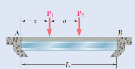
5.96 A bridge of length L = 48 ft is to be built on a secondary road whose access to trucks is limited to two-axle vehicles of medium weight. It will consist of a concrete slab and of simply supported steel beams with an ultimate strength σU = 60 ksi. The combined weight of the slab and beams can be approximated by a uniformly distributed load w = 0.75 kips/ft on each beam. For the purpose of the design, it is assumed that a truck with axles located at a distance a = 14 ft from each other will be driven across the bridge and that the resulting concentrated loads P1 and P2 exerted on each beam could be as large as 24 kips and 6 kips, respectively. Determine the most economical wide-flange shape for the beams, using LRFD with the load factors γD = 1.25, γL = 1.75 and the resistance factor ϕ = 0.9. [Hint: It can be shown that the maximum value of |ML| occurs under the larger load when that load is located to the left of the center of the beam at a distance equal to aP2/2(P1 + P2).]
Fig. P5.96
Want to see the full answer?
Check out a sample textbook solution
Chapter 5 Solutions
Mechanics of Materials, 7th Edition


- Problem 1): A circular pipe girder is constructed from 80mm external diameter and 60 mm internal diameter. Three such girders are mounted vertically one at equal angles of a circular horizontal platform which the girders support. The platform is 5 m above ground level and weighs (0.1*B) KN. The platform supports an additional central load of (0.2*B) KN. The weight of the girders may not be neglected. The density of the material from which the girders are constructed is (290*B) kg/m3. Assuming that each girder supports an equal share of the load, determine the compressive stresses set up in the material of each girder:1- At the lower point of the girder.2- At the middle point of the girder.3- At the upper point of the girder. Discuss the above values when the weights of the girders are neglected.Note: B = 39 Problem 2): A 20 mm diameter steel rod passes concentrically through a bronze tube (200+Q) mm long, 50 mm external diameter, and 40 mm internal diameter. The ends of the steel rod…arrow_forwardQ.I. An I-section beam, 150 mm wide by 250 mm deep, with flange and web of thickness 20 mm is used as a simply supported beam over a span of 7 m. The beam carries a distributed load of 6 kN/m and a concentrated load of 30 kN at mid-span. Determine: (a) the second moment of area of the cross- section of the girder, (b) the maximum stress set-up. 20 mm 150 mm B 20 mm 250 mm 20 mmarrow_forward4. For the braced beam and loading shown; (a) draw free body diagram, (b) determine the magnitude force of member BE, and (c) determine the magnitude of the force on the support A | 50 N 20 KNAM D 15 m * 1m 3 m 30° Earrow_forward
- The load on the beam shown increases uniformly from 0 at point A to w = 63 N/m at point B over a length of L= 26 meters. Determine the magnitude of the support reaction at point B. Carrow_forwardA large number of uniform and identical cantilever beams, each 1 m long and 146 N / m in weight, are used to support pipes. Consider that the length of the tubes acting under a typical ABCD beam is 1.2 m. And that tubes B and C, plus their contents, weigh 365 N / m and 510 N / m, respectively, determine the reactions at the end set in A, of the cantilever beams.arrow_forwardExample 11.8: A three hinged arch of span 16 m has its abutments A and B at depth of 4 m and 8 m helow the crown C. The arch carries the load system as shown in Fig. 11.15. Determine the horizontal thrust and vertical reactions at supports. 100 kN 200 kN W = 30 kN/m L3 m 4 m13m 4 m H AV 8 m 6 m B Н ---- 10 m -arrow_forward
- Homework A timber beam AB of length L and rectangular cross section carries a single concentrated load P at its midpoint C. (a) Show that the ratio Tm/Tm of the maximum values of the shearing and normal stresses in the beam is equal to h/2L, where h and L are, respectively, the depth and the length of the beam. (b) Determine the depth h and the width b of the beam, knowing that L = 2 m, P = 40 KN, T, = 960 kPa, and om = 12 MPa. m · L/2 C - L/2· A Вarrow_forward-2 m -2 m – 4.5 kN 1.4 kN E 2.8 kN Do G 0.5 m F 1 kN I kN B 3 m I kN. I kN A |C I 1 m '1m 1 m 1 m Fig. P6.15 and P6.16 6.16 For the Gambrel roof truss shown, determine the force in members CG and CI and in each of the members located to the right of the centerline of the truss. State whether each member is in tension or compression.arrow_forwardPROBLEM 4.The beam AB consisting of a cast iron plate of uniform thickness, b, and length, L, is to support the distributed load w(x) shown a) Knowing that the beam is to be of constant strength (fully stressed beam), express h in terms of x, L and ho. b) Determine the smallest value of ho if L=800 mm, b=25 mm, wo=300 kN/m and oall=200 MPa. w-=WoCos(ITX/2L) A ho Barrow_forward
- 1.6 (A). An 1-seetion girder is constructed from two 80 mm x 12 mm flanges joined by an 80 mm x 12 mm web. Four such girders are mounted vertically one at each corner of a horizontal platform which the girders support. The platform is 4 m above ground level and weighs 10 kN. Assuming that each girder supports an equal share of the load, determine the maximum compressive stress set up in the material of each girder when the platform supports an additional load of 15 kN. The weight of the girders may not be neglected. The density of the cast iron from which the girders are constructed is 7470 kg/m³. [2.46 MN/m²]arrow_forward1.6 (A). An I-seetion girder is constructed from two 80 mm × 12 mm flanges joined by an 80 mm x 12 mm web. Four such girders are mounted vertically one at each corner of a horizontal platform which the girders support. The platform is 4 m above ground level and weighs 10 kN. Assuming that each girder supports an equal share of the load, determine the maximum compressive stress set up in the material of each girder when the platform supports an additional load of 15 kN. The weight of the girders may not be neglected. The density of the cast iron from which the girders are constructed is 7470 kg/m³. [2.46 MN/m².]arrow_forwardQI/Beams AB Problems, BC, and CD have the cross section shown and are pin-connected at B and C. Knowing that the allowable normal stress is +110 MPa in tension and -150 MPa in compression, (a) determine the largest permissible value of P (b) determine distance a. 12.5 mm - 200 mm- 150 mm 24 m 24 m 24 m 125 mmarrow_forward
 Elements Of ElectromagneticsMechanical EngineeringISBN:9780190698614Author:Sadiku, Matthew N. O.Publisher:Oxford University Press
 Mechanics of Materials (10th Edition)Mechanical EngineeringISBN:9780134319650Author:Russell C. HibbelerPublisher:PEARSON
 Thermodynamics: An Engineering ApproachMechanical EngineeringISBN:9781259822674Author:Yunus A. Cengel Dr., Michael A. BolesPublisher:McGraw-Hill Education
 Control Systems EngineeringMechanical EngineeringISBN:9781118170519Author:Norman S. NisePublisher:WILEY
 Mechanics of Materials (MindTap Course List)Mechanical EngineeringISBN:9781337093347Author:Barry J. Goodno, James M. GerePublisher:Cengage Learning
 Engineering Mechanics: StaticsMechanical EngineeringISBN:9781118807330Author:James L. Meriam, L. G. Kraige, J. N. BoltonPublisher:WILEY