
Concept explainers
Videos
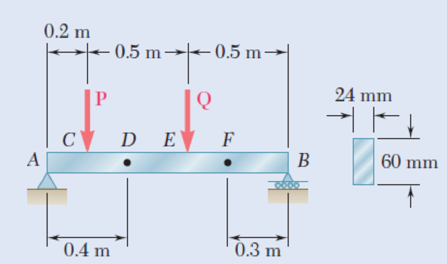
The beam AB supports two concentrated loads P and Q. The normal stress due to bending on the bottom edge of the beam is +55 MPa at D and +37.5 MPa at F. (a) Draw the shear and bending-moment diagrams for the beam. (b) Determine the maximum normal stress due to bending that occurs in the beam.
Fig. P5.62
(a)
Draw the shear and bending-moment diagrams for the beam.
Explanation of Solution
Given information:
The normal stress due to bending at the point D is
The normal stress due to bending at the point F is
Determine the section modulus (S) of the rectangular beam section using the equation.
Here, the width of the beam is b and the depth of the beam is h.
Substitute 24 mm for b and 60 mm for h.
Determine the bending moment at point D
Here, the normal stress at point D is
Substitute 55 MPa for
Determine the bending moment at point F
Here, the normal stress at point F is
Substitute 37.5 MPa for
Show the free-body diagram of the region FB as in Figure 1.

Determine the vertical reaction at point B by taking moment about point F.
Show the free body diagram of the region DEFB as in Figure 2.
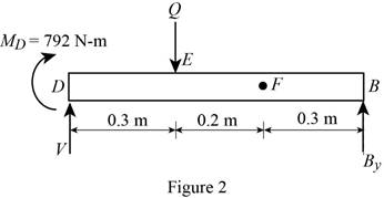
Determine the magnitude of the load Q by taking moment about the point D.
Show the free body diagram of the entire beam as in Figure 3.
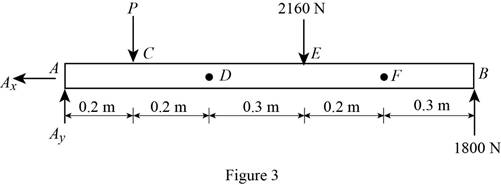
Determine the magnitude of the load P by taking moment about the point A.
Determine the vertical reaction at point A by resolving the vertical component of forces.
Shear force:
Show the calculation of shear force as follows;
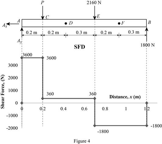
Show the calculated shear force values as in Table 1.
| Location (x) m | Shear force (V) N |
| A | 3600 |
| C (Left) | 3600 |
| C (Right) | 360 |
| E (Left) | 360 |
| E (Right) | –1800 |
| B | –1800 |
Plot the shear force diagram as in Figure 4.
Bending moment:
Show the calculation of the bending moment as follows;
Show the calculated bending moment values as in Table 2.
| Location (x) m | Bending moment (M) N-m |
| A | 0 |
| C | 720 |
| E | 900 |
| B | 0 |
Plot the bending moment diagram as in Figure 5.
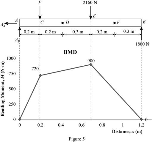
Refer to Figure 5;
The maximum absolute bending moment is
(b)
The maximum normal stress due to bending.
Answer to Problem 62P
The maximum normal stress due to bending is
Explanation of Solution
Given information:
Determine the section modulus (S) of the rectangular beam section using the equation.
Here, the width of the beam is b and the depth of the beam is h.
Substitute 24 mm for b and 60 mm for h.
The maximum absolute bending moment is
Determine the maximum normal stress
Substitute
Therefore, the maximum normal stress due to bending is
Want to see more full solutions like this?
Chapter 5 Solutions
Mechanics of Materials, 7th Edition


- A 10-ft long overhanging beam is loaded as shown. Determine the following: 10 kips 8 kips 5 kips 5 kip-ft K 3 ft -1 ft A B 2 ft . 4 ft C D E 1. Reaction at D (kips) 2. Shear at C (kips) 3. Moment at D (kip-ft) 4. Maximum shear (kips) W 5. Maximum moment (kip-ft)arrow_forwardDetermine (a) the distance a for which the absolute value of the bending moment in the beam is as small as possible, (b) the corresponding moximum normal stress due to bending.arrow_forwardA) The four cross sections shown have different characteristics when subjected to a vertical shear force. Which of the four geometries shown has the largest value for the moment of the area, Q, about the neutral axis? B) Which of the four geometries shown has the smallest value for its moment of inertia about the x axis? C) Given that all four geometries are subjected to the same vertical shear force V, which of the four has the smallest value for the maximum shear stress?arrow_forward
- Determine (a) the distance a for which the maximum absolute value of the bending moment in the beam is as small as possible, (b) the corresponding maximum normal stress due to bending.arrow_forwardA uniform live load of 1.8 kN/m and a single concentrated live force of 4 kN are placed on the floor beams. Determine (a) the maximum positive shear in panel BC of the girder and (b) the maximum moment in the girder at G.arrow_forwardDetermine the bending moment acting at each of the following locations:(a) x = 13.5- ft (i.e., just to the left of point B)(b) x = 13.5+ ft(i.e., just to the right of point B)(c) x = 17.0 ft (i.e. at point C)(d) x = 23.0 ftNote that x = 0 at support A. When entering your answers, use the shear-force sign convention detailed in Section 7.2.Answers: (a) M = kips-ft (b) M = kips-ft (c) M = kips-ft (d) M = kips-ft Use your shear-force and bending-moment diagrams to determine the maximum positive bending moment, Mmax, pos, the maximum negative bending moment, Mmax, neg, and their respective locations, xmax, pos and xmax, neg. When entering your answers for the maximum bending moments, use the shear-force and bending-moment sign conventions detailed in Section 7.2. The maximum negative bending moment is the negative moment with the largest absolute value. Enter the maximum negative bending moment as a negative value.Answers: Mmax, pos = kips-ft xmax, pos = ft Mmax,…arrow_forward
- For the beam and loading shown, determine the maximum absolute values of the shear and bending momentarrow_forwardSolve Prob. 7.89 assuming that the bending moment was found to be +650 N.m at D and +1450 N.m at E.(Reference to Problem 7.89):The beam AB is subjected to the uniformly distributed load shown and to two unknown forces P and Q . Knowing that it has been experimentally determined that the bending moment is +800 N.m at D and +1300 at E, (a) determine P and Q,(b) draw the shear and bending-moment diagrams for the beam.arrow_forwardA laminated wood beam consists of eight 2.25 in. × 5.00-in. planks glued together to form a section b = 5.00 in. wide by d = 18 in. deep, as shown and w = 663.2 lb/ft. If the allowable strength of the glue in shear is 105 psi, Determine: (c) the maximum tension bending stress in the beam when the load of part (a) is applied. [σ = 1330 psi]arrow_forward
- A 12-m simply supported overhang beam is supported at x = 0 and x = 10m. The overhanging portion is from x = 10m to x = 12m (the overhang portion is 2m). Two equal wheel loads of 20kN each, separated by 2m roll as a unit across the 12-m span. Determine the maximum shear developed in the span.arrow_forwardA solid beam supported on bearings 15 ft apart, has a cross-section of 1/2 in deep and 3/8 in wide. Determine the bending stress in the beam assuming that a load of 10 lbis applied gradually at the center of the beam length.arrow_forwardFor the beam and loading shown, consider section n–n and determine the shearing stress at (a) point a, (b) point b.arrow_forward
 Elements Of ElectromagneticsMechanical EngineeringISBN:9780190698614Author:Sadiku, Matthew N. O.Publisher:Oxford University Press
 Mechanics of Materials (10th Edition)Mechanical EngineeringISBN:9780134319650Author:Russell C. HibbelerPublisher:PEARSON
 Thermodynamics: An Engineering ApproachMechanical EngineeringISBN:9781259822674Author:Yunus A. Cengel Dr., Michael A. BolesPublisher:McGraw-Hill Education
 Control Systems EngineeringMechanical EngineeringISBN:9781118170519Author:Norman S. NisePublisher:WILEY
 Mechanics of Materials (MindTap Course List)Mechanical EngineeringISBN:9781337093347Author:Barry J. Goodno, James M. GerePublisher:Cengage Learning
 Engineering Mechanics: StaticsMechanical EngineeringISBN:9781118807330Author:James L. Meriam, L. G. Kraige, J. N. BoltonPublisher:WILEY