
Concept explainers
Videos
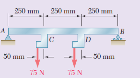
Draw the shear and bending-moment diagrams for the beam and loading shown, and determine the maximum absolute value (a) of the shear, (b) of the bending moment.
Fig. P5.152
(a)
Draw: The shear force diagram for the beam and loading.
Find the maximum absolute value of the shear.
Answer to Problem 152RP
The maximum absolute value of the shear force is
Explanation of Solution
Show the free-body diagram of the entire beam as in Figure 1.
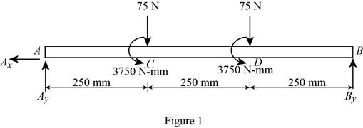
Determine the vertical reaction at point B by taking moment about point A.
Determine the vertical reaction at point A by resolving the vertical component of forces.
Show the free-body diagram of the sections as in Figure 2.

Section AC (1-1):
Determine the shear force at the section by resolving the vertical component of forces.
Section CD (2-2):
Determine the shear force at the section by resolving the vertical component of forces.
Section DB (3-3):
Determine the shear force at the section by resolving the vertical component of forces.
Show the calculated shear force values as in Table 1.
| Location (x) mm | Shear force (V) N |
| A (0 mm) | 85 |
| C (1-1) (250 mm) | 85 |
| C (2-2) (250 mm) | 10 |
| D (2-2) (500 mm) | 10 |
| D (3-3) (500 mm) | –65 |
| B (750 mm) | –65 |
Plot the shear force diagram as in Figure 3.
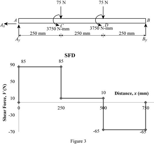
Refer to the Figure 3;
The maximum absolute value of the shear force is
(b)
Draw the bending moment diagram for the beam and loading.
Find the maximum absolute value of the bending moment.
Answer to Problem 152RP
The maximum absolute value of the bending moment is
Explanation of Solution
Show the free-body diagram of the entire beam as in Figure 4.

Determine the vertical reaction at point B by taking moment about point A.
Determine the vertical reaction at point A by resolving the vertical component of forces.
Show the free-body diagram of the sections as in Figure 5.
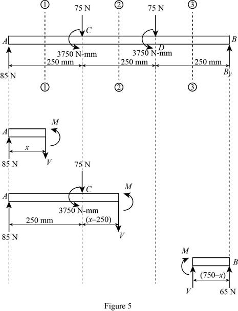
Section AC (1-1):
Determine the bending moment at the section by taking moment about the section.
Section CD (2-2):
Determine the bending moment at the section by taking moment about the section.
Section DB (3-3):
Determine the bending moment at the section by taking moment about the section.
Show the calculated bending moment values as in Table 2.
| Location (x) mm | Bending moment (V) N-mm |
| A (0 mm) | 0 |
| C (1-1) (250 mm) | 21250 |
| C (2-2) (250 mm) | 17500 |
| D (2-2) (500 mm) | 20000 |
| D (3-3) (500 mm) | 16250 |
| B (750 mm) | 0 |
Plot the bending moment diagram as in Figure 6.
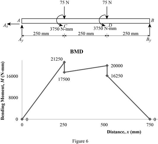
Refer to the Figure 6;
The maximum absolute value of the bending moment is,
The maximum absolute value of the bending moment is
Want to see more full solutions like this?
Chapter 5 Solutions
Mechanics of Materials, 7th Edition


- Draw the shear and bending-moment diagrams for the beam and loading shown, and determine the maximum absolute value (a) of the shear, (b) of the bendingarrow_forwardDetermine (a) the equations of the shear and bending moment curves for the beam and loading shown, (b) the maximum absolute value of the bending moment in the beam.arrow_forwardA cable AB of span L and a simple beam A'B' of the same span are subjected to identical vertical loadings as shown. Show that the magnitude of the bending moment at a point C' in the beam is equal to the product T0h, where T0 is the magnitude of the horizontal component of the tension force in the cable and h is the vertical distance between point C and the chord joining the points of support A and B.arrow_forward
- Draw the shear and bending moment diagrams for the beam and loadin g shown, and determine the maximum absolute value ( a ) of the shear, ( b ) of the bendin g moment.arrow_forwardFor the beam and loading shown, determine the maximum absolute values of the shear and bending momentarrow_forwardProblem 03: Draw the shear and bending-moment diagrams for the beam and loading shown, and determine the maximum absolute value (a) of the shear, (b) of the bending moment.arrow_forward
- For the beam and loading shown, determine the absolute values of the shear and bending moment at 2.5 m to the left of point B.arrow_forwardFor the beam and loading shown, (a) draw the shear and bending-moment diagrams, (b) determine the location and magnitude of the maximum absolute value of the bending moment.arrow_forwardFor the beam and loading shown, determine the maximum absolute value of bending moment and sheararrow_forward
- Solve Prob. 7.89 assuming that the bending moment was found to be +650 N.m at D and +1450 N.m at E.(Reference to Problem 7.89):The beam AB is subjected to the uniformly distributed load shown and to two unknown forces P and Q . Knowing that it has been experimentally determined that the bending moment is +800 N.m at D and +1300 at E, (a) determine P and Q,(b) draw the shear and bending-moment diagrams for the beam.arrow_forwardKnowing that W = 12 kN, draw the shear and bending-moment diagrams for beam AB and determine the maximum normal stress due to bending.arrow_forwardFor the beam and loading shown, determine the maximum absolute value of shear and bending moment.arrow_forward
 Elements Of ElectromagneticsMechanical EngineeringISBN:9780190698614Author:Sadiku, Matthew N. O.Publisher:Oxford University Press
 Mechanics of Materials (10th Edition)Mechanical EngineeringISBN:9780134319650Author:Russell C. HibbelerPublisher:PEARSON
 Thermodynamics: An Engineering ApproachMechanical EngineeringISBN:9781259822674Author:Yunus A. Cengel Dr., Michael A. BolesPublisher:McGraw-Hill Education
 Control Systems EngineeringMechanical EngineeringISBN:9781118170519Author:Norman S. NisePublisher:WILEY
 Mechanics of Materials (MindTap Course List)Mechanical EngineeringISBN:9781337093347Author:Barry J. Goodno, James M. GerePublisher:Cengage Learning
 Engineering Mechanics: StaticsMechanical EngineeringISBN:9781118807330Author:James L. Meriam, L. G. Kraige, J. N. BoltonPublisher:WILEY