
Concept explainers
Videos
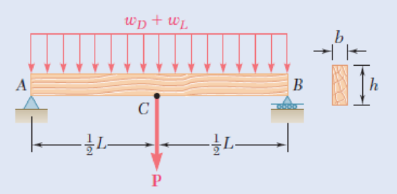
Solve Prob. 5.94, assuming that the 6-kN concentrated load P applied to each beam is replaced by 3-kN concentrated loads P1 and P2 applied at a distance of 4 m from each end of the beams.
5.94 A roof structure consists of plywood and roofing material supported by several timber beams of length L = 16 m. The dead load carried by each beam, including the estimated weight of the beam, can be represented by a uniformly distributed load wD = 350 N/m. The live load consists of a snow load, represented by a uniformly distributed load wL = 600 N/m, and a 6-kN concentrated load P applied at the midpoint C of each beam. Knowing that the ultimate strength for the timber used is σU = 50 MPa and that the width of the beam is b = 75 mm, determine the minimum allowable depth h of the beams, using LRFD with the load factors γD = 1.2, γL = 1.6 and the resistance factor ϕ = 0.9.
Fig. P5.94
Want to see the full answer?
Check out a sample textbook solution
Chapter 5 Solutions
Mechanics of Materials, 7th Edition


- PROBLEM 1: The 1500-kg beam ABC has fixed support at A and connected to beam BD by hinge at B. Beam BD has a mass of 2000 kg and supported by a cable at D. The cable is attached to the 20-cm-diameter pulley at E and pulled vertically at the other end, by tension T. Given: a = 1.5 m; b = 0.9 m; c = 1.8 m d = 0.6 m; e = 1.4 m; θ = 75°. Calculate the required tension to maintain in equilibrium. (ANSWER: 12.830KN) Calculate the moment reaction at A. (ANSWER: 28.499) Calculate the total reaction at A. (ANSWER: 22.192) Calculate the vertical reaction at E. (ANSWER: 25.223)arrow_forwardProblem 5 Rigid member ABC is supported with two links BE and CD which have a cross section area of 230 and 300 mm? respectively. Determine the maximum applied force Q knowing that the maximum movement of point E is 0.45 mm. D Brass E - 105 GPa 230 mm B C E Aluminum E = 70 GPa 150 mm 65 mm 230 mm Area given is for member AB not BE Cross section area of links AB and CD are 230 and 300 mm^2 respectively.arrow_forwardA transmission tower is held by three guy wires attached to a pin at A and anchored by bolts at B, C, and D. If the tension in wire AC is 413 Ib, determine the vertical force P exerted by the tower on the pin at A. 100 ft D 20 ft 25 ft B 74 ft 20 ft 60 ft `18 ft The vertical force P exerted by the tower on the pin at A is Ib.arrow_forward
- For the beam and loading shown, determine the vertical reaction at A (Ib) provided that a=156, b=118, c=6 and d=3. Round off only on the final answer expressed in 3 decimal places. a lb/ft |b lb/ft A B В d ft- c ft-arrow_forwardA beam ABCD, 6 m long, is simply-supported at the right-hand end D and at a point B 1 m from the left hand end A. It carries a vertical load of 10 kN at A, a second concentrated load of 20 kN at C, 3 m from D, and a uniformly distributed load of 10 kN/m between C and D. Determine the position and magnitude of the maximum deflection if E = 208 GN/m2 and I = 35 x10^-6 m4.arrow_forward2. For the beam shown: a. Draw the free-body diagram of the beam. b. Determine the reactions at the supports. 1.8 m | 1.8m | 1¹ 4 0.80 KN 1.5m₂ 2.1m 1.38 kN 25⁰arrow_forward
- 96 Fundamentals of Biomechanics Determine the tensions T1 and T2 in the cables, weights W, and W2, and angle a that cable 1 makes with the horizontal, so that the leg remains in equilibrium at the position shown. Answers: T1 W1 = 223.6N T2= W2 = 282.8N a= 26.6° Problem 4.10 Consider the uniform, horizontal cantilever beam shown in Fig. 4.56. The beam is fixed at point A and a force that makes an angle B= 63° with the horizontal is applied at point B. The magnitude of the applied force is P=80 N. Point C is the center of gravity of the beam and the beam weighs W = 40 N and has a length 1 = 2 m. L. Fig. 4.56 Problem 4.10 Determine the reactions generated at the fixed end of the beam. Answers: RAr=36.3N (+x) RAy=111.3N(+y) MA=182.6 Mm (ccw) %3D %3D Problem 4.11 Consider the L-shaped beam illustrated in Fig. 4.57. The beam is welded to the wall at point A, the arm AB extends in the positive z direction, and the arm BC extends in the negative y direction. A force P is applied in the…arrow_forwardExercise 2.5 • The rods AB and CD are made of steel and the beam is assumed to be pin connected at A and C. Determine the forces exert upon rods AB and CD. Neglect the weight of the beam in the calculations. B 6 kN Į ^ 1-2m-+-2m-+-- 4 kN -3 m- 5 KN 3 m- (D C Answ: FCD = 6.7 kN FAB = 8.3 KNarrow_forwardThree loads are applied to a beam as shown. The beam is supported by a roller at A and by a pin at B. Neglecting the weight of the beam, determine the reactions at A and B when P = 15 kips 6 kips 6 kips B 6 ft 3 ft 2 ft ' 2 ftarrow_forward
- A cable with supports at the same elevation has a span of 400 m. The cable supports a uniformly distributed load of 6 kN/m along the horizontal. The maximum ten- sion in the cable is 5000 kN. Determine The angle between the cable and the horizontal at a support.arrow_forwardThe beam CBA is supported by a ball and socket support at C and two cables AD,AE as shown. It is loaded by two forces F=918 KN and P=306 KN. 0.8 m 0.8 m D 0.6 m E 1.2 m B. 1.2 m y F 1.2 m Tension in cable AD (KN) Tension in cable AE (KN) magnitude of Cx (KN) magnitude of Cy (KN) magnitude of C2 (KN) Narrow_forwardII. A rope is looped over the two fixed posts each of 16 cm diameter as shown. If u == determine the maximum and minimum values of P that will prevent motion of load W=1200 KN. 14 Cm 14cm (200arrow_forward
 Elements Of ElectromagneticsMechanical EngineeringISBN:9780190698614Author:Sadiku, Matthew N. O.Publisher:Oxford University Press
 Mechanics of Materials (10th Edition)Mechanical EngineeringISBN:9780134319650Author:Russell C. HibbelerPublisher:PEARSON
 Thermodynamics: An Engineering ApproachMechanical EngineeringISBN:9781259822674Author:Yunus A. Cengel Dr., Michael A. BolesPublisher:McGraw-Hill Education
 Control Systems EngineeringMechanical EngineeringISBN:9781118170519Author:Norman S. NisePublisher:WILEY
 Mechanics of Materials (MindTap Course List)Mechanical EngineeringISBN:9781337093347Author:Barry J. Goodno, James M. GerePublisher:Cengage Learning
 Engineering Mechanics: StaticsMechanical EngineeringISBN:9781118807330Author:James L. Meriam, L. G. Kraige, J. N. BoltonPublisher:WILEY