
Mechanics of Materials, 7th Edition
7th Edition
ISBN: 9780073398235
Author: Ferdinand P. Beer, E. Russell Johnston Jr., John T. DeWolf, David F. Mazurek
Publisher: McGraw-Hill Education
expand_more
expand_more
format_list_bulleted
Concept explainers
Videos
Textbook Question
Chapter 5.3, Problem 91P
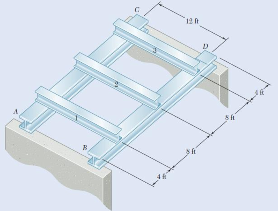
Each of the three rolled-steel beams shown (numbered 1, 2, and 3) is to carry a 64-kip load uniformly distributed over the beam. Each of these beams has a 12-ft span and is to be supported by the two 24-ft rolled-steel girders AC and BD. Knowing that the allowable normal stress for the steel used is 24 ksi, select (a) the most economical S shape for the three beams, (b) the most economical W shape for the two girders.
Fig. P5.91
Expert Solution & Answer
Want to see the full answer?
Check out a sample textbook solution
Students have asked these similar questions
Q.I. An I-section beam, 150 mm wide by 250 mm deep, with flange and
web of thickness 20 mm is used as a simply supported beam over a span of 7
m. The beam carries a distributed load of 6 kN/m and a concentrated load of
30 kN at mid-span. Determine: (a) the second moment of area of the cross-
section of the girder, (b) the maximum stress set-up.
20 mm
150 mm
B
20 mm
250 mm
20 mm
Problem 1: A 10 ft. long simply supported laminated wooden beam consists of eight 1.5in. by 6 in. planks glued
together to form a section 6 in. by 12 in. deep, as shown. The beam carries a 9 kip concentrated load at midspan.
At section a-a, located 2.5 ft. from pin support A, determine:
a) The horizontal shear stress in the glue joints at b, c, and d.
b) The maximum horizontal shear stress in the cross section.
9 kips
A
2.5 ft
a
5 ft
B
5 ft
O
1.5 in.
(typ)
12 in.
6 in.
b
с
d
2. A cover-plate beam is made up of an I-Beam section with 300 mm x 12 mm plates attached to the top
and bottom flanges and is fastened by two rows of 20 mm rivets. The beam is simply supported over a
span of 6m and carries a uniformly distributed load of 270 kN/m including its own weight.
a. Determine the distance from the centroid of the cover plate to the neutral axis of the built-up
section.
b. Determine the moment of inertia of the built-up section about its neutral axis.
c. Determine the maximum flexural stress of the built-up section.
200 mm
30 mm
310 mm
30 mm
30 mm
Chapter 5 Solutions
Mechanics of Materials, 7th Edition
Ch. 5.1 - 5.1 through 5.6 For the beam and loading shown,...Ch. 5.1 - 5.1 through 5.6 For the beam and loading shown,...Ch. 5.1 - 5.1 through 5.6 For the beam and loading shown,...Ch. 5.1 - 5.1 through 5.6 For the beam and loading shown,...Ch. 5.1 - 5.1 through 5.6 For the beam and loading shown,...Ch. 5.1 - 5.1 through 5.6 For the beam and loading shown,...Ch. 5.1 - 5.7 and 5.8 Draw the shear and bending-moment...Ch. 5.1 - 5.7 and 5.8 Draw the shear and bending-moment...Ch. 5.1 - 5.9 and 5.10 Draw the shear and bending-moment...Ch. 5.1 - 5.9 and 5.10 Draw the shear and bending-moment...
Ch. 5.1 - 5.11 and 5.12 Draw the shear and bending-moment...Ch. 5.1 - 5.11 and 5.12 Draw the shear and bending-moment...Ch. 5.1 - 5.13 and 5.14 Assuming that the reaction of the...Ch. 5.1 - 5.13 and 5.14 Assuming that the reaction of the...Ch. 5.1 - 5.15 and 5.16 For the beam and loading shown,...Ch. 5.1 - 5.15 and 5.16 For the beam and loading shown,...Ch. 5.1 - For the beam and loading shown, determine the...Ch. 5.1 - For the beam and loading shown, determine the...Ch. 5.1 - 5.19 and 5.20 For the beam and loading shown,...Ch. 5.1 - 5.19 and 5.20 For the beam and loading shown,...Ch. 5.1 - Draw the shear and bending-moment diagrams for the...Ch. 5.1 - 5.22 and 5.23 Draw the shear and bending-moment...Ch. 5.1 - 5.22 and 5.23 Draw the shear and bending-moment...Ch. 5.1 - 5.24 and 5.25 Draw the shear and bending-moment...Ch. 5.1 - 5.24 and 5.25 Draw the shear and bending-moment...Ch. 5.1 - Knowing that W = 12 kN, draw the shear and...Ch. 5.1 - Determine (a) the magnitude of the counterweight W...Ch. 5.1 - Determine (a) the distance a for which the...Ch. 5.1 - Knowing that P = Q = 480 N, determine (a) the...Ch. 5.1 - Solve Prob. 5.29, assuming that P = 480 N and Q =...Ch. 5.1 - Determine (a) the distance a for which the...Ch. 5.1 - A solid steel rod of diameter d is supported as...Ch. 5.1 - A solid steel bar has a square cross section of...Ch. 5.2 - Using the method of Sec. 5.2, solve Prob. 5.1a....Ch. 5.2 - Using the method of Sec. 5.2, solve Prob. 5.2a....Ch. 5.2 - Prob. 36PCh. 5.2 - Prob. 37PCh. 5.2 - Using the method of Sec. 5.2, solve Prob. 5.5a....Ch. 5.2 - Using the method of Sec. 5.2, solve Prob. 5.6a....Ch. 5.2 - Using the method of Sec. 5.2, solve Prob. 5.7. 5.7...Ch. 5.2 - Using the method of Sec. 5.2, solve Prob. 5.8. 5.7...Ch. 5.2 - Prob. 42PCh. 5.2 - Using the method of Sec. 5.2, solve Prob. 5.10....Ch. 5.2 - 5.44 and 5.45 Draw the shear and bending-moment...Ch. 5.2 - 5.44 and 5.45 Draw the shear and bending-moment...Ch. 5.2 - Prob. 46PCh. 5.2 - Prob. 47PCh. 5.2 - Prob. 48PCh. 5.2 - Using the method of Sec. 5.2, solve Prob. 5.20....Ch. 5.2 - 5.50 and 5.51 Determine (a) the equations of the...Ch. 5.2 - 5.50 and 5.51 Determine (a) the equations of the...Ch. 5.2 - 5.52 and 5.53 Determine (a) the equations of the...Ch. 5.2 - 5.52 and 5.53 Determine (a) the equations of the...Ch. 5.2 - 5.54 and 5.55 Draw the shear and bending-moment...Ch. 5.2 - 5.54 and 5.55 Draw the shear and bending-moment...Ch. 5.2 - 5.56 and 5.57 Draw the shear and bending-moment...Ch. 5.2 - 5.56 and 5.57 Draw the shear and bending-moment...Ch. 5.2 - 5.58 and 5.59 Draw the shear and bending-moment...Ch. 5.2 - 5.58 and 5.59 Draw the shear and bending-moment...Ch. 5.2 - Knowing that beam AB is in equilibrium under the...Ch. 5.2 - Knowing that beam AB is in equilibrium under the...Ch. 5.2 - The beam AB supports two concentrated loads P and...Ch. 5.2 - The beam AB supports a uniformly distributed load...Ch. 5.2 - Beam AB supports a uniformly distributed load of 2...Ch. 5.3 - 5.65 and 5.66 For the beam and loading shown,...Ch. 5.3 - 5.65 and 5.66 For the beam and loading shown,...Ch. 5.3 - 5.67 and 5.68 For the beam and loading shown,...Ch. 5.3 - 5.67 and 5.68 For the beam and loading shown,...Ch. 5.3 - 5.69 and 5.70 For the beam and loading shown,...Ch. 5.3 - 5.69 and 5.70 For the beam and loading shown,...Ch. 5.3 - 5.71 and 5.72 Knowing that the allowable normal...Ch. 5.3 - 5.71 and 5.72 Knowing that the allowable normal...Ch. 5.3 - 5.73 and 5.74 Knowing that the allowable normal...Ch. 5.3 - 5.73 and 5.74 Knowing that the allowable normal...Ch. 5.3 - 5.75 and 5.76 Knowing that the allowable normal...Ch. 5.3 - 5.75 and 5.76 Knowing that the allowable normal...Ch. 5.3 - 5.77 and 5.78 Knowing that the allowable normal...Ch. 5.3 - 5.77 and 5.78 Knowing that the allowable normal...Ch. 5.3 - A steel pipe of 100-mm diameter is to support the...Ch. 5.3 - Two metric rolled-steel channels are to be welded...Ch. 5.3 - Two rolled-steel channels are to be welded back to...Ch. 5.3 - Two L4 3 rolled-steel angles are bolted together...Ch. 5.3 - Assuming the upward reaction of the ground to be...Ch. 5.3 - Assuming the upward reaction of the ground to be...Ch. 5.3 - Determine the largest permissible distributed load...Ch. 5.3 - Solve Prob. 5.85, assuming that the cross section...Ch. 5.3 - Determine the largest permissible value of P for...Ch. 5.3 - Solve Prob. 5.87, assuming that the T-shaped beam...Ch. 5.3 - Beams AB, BC, and CD have the cross section shown...Ch. 5.3 - Beams AB, BC, and CD have the cross section shown...Ch. 5.3 - Each of the three rolled-steel beams shown...Ch. 5.3 - A 54-kip load is to be supported at the center of...Ch. 5.3 - A uniformly distributed load of 66 kN/m is to be...Ch. 5.3 - A roof structure consists of plywood and roofing...Ch. 5.3 - Solve Prob. 5.94, assuming that the 6-kN...Ch. 5.3 - Prob. 96PCh. 5.3 - Assuming that the front and rear axle loads remain...Ch. 5.4 - 5.98 through 5.100 (a) Using singularity...Ch. 5.4 - 5.98 through 5.100 (a) Using singularity...Ch. 5.4 - 5.98 through 5.100 (a) Using singularity...Ch. 5.4 - 5.101 through 5.103 (a) Using singularity...Ch. 5.4 - Prob. 102PCh. 5.4 - Prob. 103PCh. 5.4 - Prob. 104PCh. 5.4 - Prob. 105PCh. 5.4 - Prob. 106PCh. 5.4 - Prob. 107PCh. 5.4 - Prob. 108PCh. 5.4 - Prob. 109PCh. 5.4 - Prob. 110PCh. 5.4 - Prob. 111PCh. 5.4 - Prob. 112PCh. 5.4 - 5.112 and 5.113 (a) Using singularity functions,...Ch. 5.4 - Prob. 114PCh. 5.4 - 5.114 and 5.115 A beam is being designed to be...Ch. 5.4 - 5.116 and 5.117 A timber beam is being designed to...Ch. 5.4 - Prob. 117PCh. 5.4 - Prob. 118PCh. 5.4 - Prob. 119PCh. 5.4 - 5.118 through 5.121 Using a computer and step...Ch. 5.4 - Prob. 121PCh. 5.4 - 5.122 and 5.123 For the beam and loading shown and...Ch. 5.4 - 5.122 and 5.123 For the beam and loading shown and...Ch. 5.4 - 5.124 and 5.125 For the beam and loading shown and...Ch. 5.4 - Prob. 125PCh. 5.5 - 5.126 and 5.127 The beam AB, consisting of a...Ch. 5.5 - Prob. 127PCh. 5.5 - 5.128 and 5.129 The beam AB, consisting of a...Ch. 5.5 - 5.128 and 5.129 The beam AB, consisting of a...Ch. 5.5 - Prob. 130PCh. 5.5 - Prob. 131PCh. 5.5 - Prob. 132PCh. 5.5 - 5.132 and 5.133 A preliminary design on the use of...Ch. 5.5 - Prob. 134PCh. 5.5 - Prob. 135PCh. 5.5 - Prob. 136PCh. 5.5 - Prob. 137PCh. 5.5 - Prob. 138PCh. 5.5 - Prob. 139PCh. 5.5 - Assuming that the length and width of the cover...Ch. 5.5 - Two cover plates, each 12 in. thick, are welded to...Ch. 5.5 - Two cover plates, each 12 in. thick, are welded to...Ch. 5.5 - Prob. 143PCh. 5.5 - Prob. 144PCh. 5.5 - Two cover plates, each 7.5 mm thick, are welded to...Ch. 5.5 - Prob. 146PCh. 5.5 - Prob. 147PCh. 5.5 - For the tapered beam shown, determine (a) the...Ch. 5.5 - Prob. 149PCh. 5.5 - Prob. 150PCh. 5.5 - Prob. 151PCh. 5 - Draw the shear and bending-moment diagrams for the...Ch. 5 - Draw the shear and bending-moment diagrams for the...Ch. 5 - Determine (a) the distance a for which the...Ch. 5 - For the beam and loading shown, determine the...Ch. 5 - Draw the shear and bending-moment diagrams for the...Ch. 5 - Beam AB, of length L and square cross section of...Ch. 5 - Prob. 158RPCh. 5 - Knowing that the allowable normal stress for the...Ch. 5 - Prob. 160RPCh. 5 - (a) Using singularity functions, find the...Ch. 5 - Prob. 162RPCh. 5 - Prob. 163RP
Knowledge Booster


Learn more about
Need a deep-dive on the concept behind this application? Look no further. Learn more about this topic, mechanical-engineering and related others by exploring similar questions and additional content below.Similar questions
- 24 kips Knowing that the allowable normal stress for the steel used is 24 ksi, select the most economical wide-flange beam to support the loading shown. 2.75 kips/ft B - ft 15 ftarrow_forwardQI/Beams AB Problems, BC, and CD have the cross section shown and are pin-connected at B and C. Knowing that the allowable normal stress is +110 MPa in tension and -150 MPa in compression, (a) determine the largest permissible value of P (b) determine distance a. 12.5 mm -200 mm- 150 mm 24 m 2.4 m 2.4 m --l|- 12.5 mmarrow_forwardA couple M will be applied to a beam of rectangular cross section that is to be sawed from a log of circular cross section. Determine the ratio d/b for which (a) the maximum stress σm will be as small as pos-sible, (b) the radius of curvature of the beam will be maximum.arrow_forward
- Problem 3 (a) Using an allowable stress of 120 MPa, determine the largest couple M that can be applied to a beam of the cross section shown. (b) Solve part a, assuming that the cross section of the beam is an 80-mm square. 10 mm M 80 mm 10 mm 80 1 mm 5 mm 5 mmarrow_forwardKnowing that the allowable normal stress for the steel used is 24 ksi, select the most economical S-shape beam to support the loading shown.arrow_forwardKnowing that the allowable normal stress for the steel used is 160 MPa, select the most economical wide-flange beam to support the loading shown.arrow_forward
- Knowing that the average normal stress in member EF of the Pratt bridge truss shown must not exceed 8.36 ksi for the given loading, determine the cross-sectional area (in sq. in) of this member that will yield the most economical and safe design if h = 14.2 ft and P = 87.28 kips.arrow_forwardKnowing that the allowable normal stress for the steel used is 160 MPa, select the most economical S-shape beam to support the loading shown.arrow_forwardDetermine the largest permissible value of P for the beam and loading shown, knowing that the allowable normal stress is +4 ksi in tension and -9 ksi in compression. Solve for P (Note: Draw the shear and moment diagram). |P |P 1 in. -10 in. 10 in- A E 5 in. B |C D 1 in. 7 in. 60 in. 60 in.arrow_forward
- For the beam and loading shown, design the cross section of the beam, knowing that the grade of timber used has an allowable normal stress of 9 MPa. b = mm 4 kN/m 150 mm 3.4 m 1.0 marrow_forwardKnowing that the allowable normal stress for the steel used is 24 ksi, select the most economical wide-flange beam to support the loading shownarrow_forwardA 1600-lb-in. couple is applied to a wooden beam, of rectangular cross section 1.5 by 3.5 in., in a plane forming an angle of 308 with the vertical (Fig. ). Determine (a) the maximum stress in the beam and (b) the angle that the neutral surface forms with the horizontal planearrow_forward
arrow_back_ios
SEE MORE QUESTIONS
arrow_forward_ios
Recommended textbooks for you
 Elements Of ElectromagneticsMechanical EngineeringISBN:9780190698614Author:Sadiku, Matthew N. O.Publisher:Oxford University Press
 Mechanics of Materials (10th Edition)Mechanical EngineeringISBN:9780134319650Author:Russell C. HibbelerPublisher:PEARSON
 Thermodynamics: An Engineering ApproachMechanical EngineeringISBN:9781259822674Author:Yunus A. Cengel Dr., Michael A. BolesPublisher:McGraw-Hill Education
 Control Systems EngineeringMechanical EngineeringISBN:9781118170519Author:Norman S. NisePublisher:WILEY
 Mechanics of Materials (MindTap Course List)Mechanical EngineeringISBN:9781337093347Author:Barry J. Goodno, James M. GerePublisher:Cengage Learning
 Engineering Mechanics: StaticsMechanical EngineeringISBN:9781118807330Author:James L. Meriam, L. G. Kraige, J. N. BoltonPublisher:WILEY
Elements Of Electromagnetics
Mechanical Engineering
ISBN:9780190698614
Author:Sadiku, Matthew N. O.
Publisher:Oxford University Press
Mechanics of Materials (10th Edition)
Mechanical Engineering
ISBN:9780134319650
Author:Russell C. Hibbeler
Publisher:PEARSON
Thermodynamics: An Engineering Approach
Mechanical Engineering
ISBN:9781259822674
Author:Yunus A. Cengel Dr., Michael A. Boles
Publisher:McGraw-Hill Education
Control Systems Engineering
Mechanical Engineering
ISBN:9781118170519
Author:Norman S. Nise
Publisher:WILEY
Mechanics of Materials (MindTap Course List)
Mechanical Engineering
ISBN:9781337093347
Author:Barry J. Goodno, James M. Gere
Publisher:Cengage Learning
Engineering Mechanics: Statics
Mechanical Engineering
ISBN:9781118807330
Author:James L. Meriam, L. G. Kraige, J. N. Bolton
Publisher:WILEY
Engineering Basics - Statics & Forces in Equilibrium; Author: Solid Solutions - Professional Design Solutions;https://www.youtube.com/watch?v=dQBvQ2hJZFg;License: Standard YouTube License, CC-BY