
Concept explainers
Videos
The maximum normal stress due to bending on section a-a.
Answer to Problem 48P
The maximum normal stress due to bending on section a-a is
Explanation of Solution
Show the free-body diagram of the entire beam as in Figure 1.
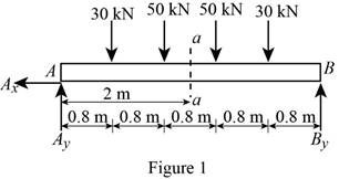
Determine the vertical reaction at point A by taking moment about point B.
Determine the vertical reaction at point B by resolving the vertical component of forces.
Determine the horizontal direction at point A by resolving the horizontal component of forces.
Shear force:
Show the calculation of shear force as follows;
Bending moment:
Show the calculation of bending moment as follows;
The bending moment at the section a-a is
Refer to Appendix C “Properties of Rolled-Steel Sections” in the textbook.
The section modulus for
Determine the maximum normal stress
Substitute
Therefore, the maximum normal stress due to bending on section a-a is
Want to see more full solutions like this?
Chapter 5 Solutions
Mechanics of Materials, 7th Edition


- Determine (a) the distance a for which the absolute value of the bending moment in the beam is as small as possible, (b) the corresponding moximum normal stress due to bending.arrow_forwardA weightlifting bar is loaded symmetrically in A and D (P = 1500N of each side). The weightlifter's hands are located at B and C, 0.45 m from A and D. Determine the maximum bending moment in the bar ABCD and the minimum diameter d of the bar knowing that the constraint admissible for the material of the bar is 200MPa.arrow_forwardA beam consists of three planks connected by steel bolts with a lon-gitudinal spacing of 225 mm. Knowing that the shear in the beam is vertical and equal to 6 kN and that the allowable average shearing stress in each bolt is 60 MPa, determine the smallest permissible bolt diameter that can be usedarrow_forward
- For the wide-flange beam with the loading shown, determine the largest load P that can be applied, knowing that the maximum normal stress is 160 MPa and the largest shearing stress is 100 MPa. W360 x 122 Barrow_forwardThree boards, each of 1.5 x3.5-in. rectangular cross section, are nailed together to form a beam that is subjected to a vertical shear of 250 lb. Knowing that the spacing between each pair of nails is 2.5 in., determine the shearing force in each nail.arrow_forwardA solid steel rod of diameter d is supported as shown. Knowing that for steel γ= 490 lb/ft3, determine the smallest diameter d that can be used if the normal stress due to bending is not to exceed 4 ksiarrow_forward
- Four L102 x 102 x 9.5 steel angle shapes and a 12 x 400-mm steel plate are bolted together to form a beam with the cross section shown. The bolts are of 22-mm diameter and are spaced longitudinally every 120 mm. Knowing that the beam is subjected to a vertical shear of 240 kN, determine the average shearing stress in each bolt.arrow_forwardThree 1 x 18-in. steel plates are bolted to four L6 x 6 x 1 angles to form a beam with the cross section shown. The bolts have a 78-in. diameter and are spaced longitudinally every 5 in. Knowing that the allowable average shearing stress in the bolts is 12 ksi, determine the largest permissible vertical shear in the beam. (Given: Ix= 6123 in4.)arrow_forwardFor the beam and loading shown, determine the equations of the shear and bending-moment curves and the maximum absolute value of the bending moment in the beam, knowing that (a) k= 1, (b) k= 0.5.arrow_forward
- Link AB, of width b = 50 mm and thickness t = 6 mm, is used to support the end of a horizontal beam. Knowing that the average normal stress in the link is –140 MPa, and that the average shearing stress in each of the two pins is 80 MPa, determine (a) the diameter d of the pins, (b) the average bearing stress in the link.arrow_forwardA timber beam AB of length L and rectangular cross section carries a single concentrated load P at its midpoint C. (a) Show that the ratio Tm/ m of the maximum values of the shearing and normal stresses in the beam is equal to h/2L, where h and L are, respectively, the depth and the length of the beam. (b) Determine the depth h and the width b of the beam, knowing that L = 2 m, P = 40 kN, 7m = 960 kPa, and om = 12 MPa.arrow_forwardtwo 20 x 100-mm and two 20 x 180 mm boards are glued together as shown to form a 120 x 200 mm box beam. Knowing that the beams are subjected to a vertical shear of 3.625 kN. Determin the average shearing stress in the glued joint at Barrow_forward
 Elements Of ElectromagneticsMechanical EngineeringISBN:9780190698614Author:Sadiku, Matthew N. O.Publisher:Oxford University Press
 Mechanics of Materials (10th Edition)Mechanical EngineeringISBN:9780134319650Author:Russell C. HibbelerPublisher:PEARSON
 Thermodynamics: An Engineering ApproachMechanical EngineeringISBN:9781259822674Author:Yunus A. Cengel Dr., Michael A. BolesPublisher:McGraw-Hill Education
 Control Systems EngineeringMechanical EngineeringISBN:9781118170519Author:Norman S. NisePublisher:WILEY
 Mechanics of Materials (MindTap Course List)Mechanical EngineeringISBN:9781337093347Author:Barry J. Goodno, James M. GerePublisher:Cengage Learning
 Engineering Mechanics: StaticsMechanical EngineeringISBN:9781118807330Author:James L. Meriam, L. G. Kraige, J. N. BoltonPublisher:WILEY