
Machine Elements in Mechanical Design (6th Edition) (What's New in Trades & Technology)
6th Edition
ISBN: 9780134441184
Author: Robert L. Mott, Edward M. Vavrek, Jyhwen Wang
Publisher: PEARSON
expand_more
expand_more
format_list_bulleted
Videos
Textbook Question
Chapter 5, Problem 71P
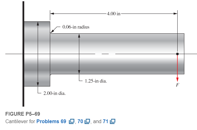
For the cantilever described in Problem 69, specify a suitable material to achieve a design factor of at least 3.0 without changing the geometry of the beam.
Expert Solution & Answer
Want to see the full answer?
Check out a sample textbook solution
Students have asked these similar questions
Given the configuration in Figure 1, calculate the load that can be supported under the following
design conditions:
(a) The pin at point R, enlarged in Figure 2, is 10.0 mm diameter. What load can be supported
by the pin if the ultimate shear strength of the pin is 195 MPa and a safety factor of 2.0 based
on ultimate strength is required?
(b) Using the load condition from (a), size cable ST if it has a design stress of 207.5 MPa.
6.00 m
75.0°
Load
2.00 m
R
Figure 1
Force
Figure 2
A structural support for a machine is subjected to a static compression load of 20 kN. The support is
manufactured from a circular rod made from SAE 1040 Hot Rolled steel. Specify suitable diameter for the
cross section of the rod based on the basic size. Steel data are available in Table A-10 from the textbook.
Using the results of problem 2, plot the shear force as a function of the shaft diameter using an Excel sheet. (5 mm (< or= to) D (< or= to) 100 mm)
Chapter 5 Solutions
Machine Elements in Mechanical Design (6th Edition) (What's New in Trades & Technology)
Ch. 5 - A link in a mechanism is made from a round bar...Ch. 5 - A link in a packaging machine mechanism has a...Ch. 5 - A cantilevered boom is part of an assembly machine...Ch. 5 - For Problems1014, use the method outlined in...Ch. 5 - For Problems1014, use the method outlined in...Ch. 5 - Figure P524shows a hydraulic cylinder that pushes...Ch. 5 - The shaft shown in Figure P528is supported by...Ch. 5 - An aluminum rod, made from alloy 6061-T6, is made...Ch. 5 - A circular bar of SAE 4140 OQT 1000 steel steps...Ch. 5 - Compute the torsional shear stress in a circular...
Knowledge Booster


Learn more about
Need a deep-dive on the concept behind this application? Look no further. Learn more about this topic, mechanical-engineering and related others by exploring similar questions and additional content below.Similar questions
- If the shape in problem 5 is used for a beam with Mmax = 25 k-ft, what is the maximum bending stress?arrow_forwardProblem 8: Complete the design of the beam shown in figure below to carry a large hydraulic motor. The beam is attached to the two side rails of the frame of a truck. Because of the vertical accelerations experienced by the truck, the load on the beam varies from 1200 lb upward to 5000 lb downward. One-half of the load is applied to the beam by each foot of the motor. Hydraulic motor Side rail of truck Beam to be designed -16 in -50 in 16 inarrow_forwardPROBLEM:1 A gas engine valve spring is to have a mean diameter of 55 mm. The maximum load it will have to sustain is 584 N with a corresponding deflection of 7.18 mm. The spring is to be made of tempered wire. Since the material is to be subjected to repeated loading and fatigue must be considered a low working stress of 650 N/mm? will be used. Find the size for wire and number of coils used. Take modulus of rigidity as 0.84 x 10⁵ N/mm? .Assume the spring coil is squared and ground. Take shear stress Concentration factor as 1.15.arrow_forward
- Compute the design factor in the middle portion only of the rod AC if the steady vertical force on the boom is 2500 lb. The rod is rectangular, 1.50 in by 3.50 in, and is made from SAE 1144 cold-drawn steel. Include a mohr circle.arrow_forward31. A beam is simply supported and carries the load shown in Figure P3–31. Specify suitable dimensions for the beam if it is steel and the stress is limited to 18 000 psi, for the following shapes: (a) Square (b) Rectangle with height three times the width (c) Rectangle with height one-third the width (d) Solid circular section (e) American Standard beam section (f) American Standard channel with the legs down (g) Standard steel pipe F | 1200 lb 1200 lb 3 ft 4 ft 3 ft R1 R2 IGURE P3–31 (Problems 31, 32, and 33)arrow_forwardQUESTION 2 A 13-kN hydraulic press for removing and reinstalling bearings in small-to medium-sized electric motors is to consist of a commercially available cylinder mounted vertically in a C- frame, with dimensions as sketched in the Figure shown below. It is being proposed to use ASTM A-48 (Class 50) gray cast iron (brittle material with ultimate strength, Su 345 MPa) for the C-frame material. Calculate the bending moment about the centroidal axis upto 3 digits after decimal point in KN.m? 18 mm 38 mm 13 kN 25 mm 10 mm -90 mm 10 mm 1.805 Save A Click Save and Submit to save and submit. Click Save All Answers to save all answers. arch DELLarrow_forward
- A vertical channel 152 x 76 (see Table A-7) has a cantilever beam bolted to it as shown. The channel is hot-rolled AISI 1006 steel. The bar is of hot-rolled AISI 1015 steel. The shoulder bolts are M10 x 1.5 ISO 5.8. Assume the bolt threads do not extend into the joint. For a design factor of 2.2, find the safe force Fthat can be applied to the cantilever. 12 50 +50--50-- 26! 125 The maximum allowable force on the system Fis N.arrow_forwardPlease answer in this format. Sketch: Given: Required: Solution: (Please answer in detailed (step by step). Indicate labels on what you are doing/performing, for example what formula is used) A torque To is transmitted between two flanged shafts by means of four 20-mm bolts. diameter of the bolt circle is 2=150mm. If the allowable shear stress in the bolts is 90 Mpa, what is the maximum permissible torque? Disregard friction between between flanges. The Toarrow_forwardSteady loading has design factor of 2 & design shear stress of (yield strength divided by 4)arrow_forward
- 10) A screw clamp similar to the one shown in the figure has a handle with diameter in made of cold-drawn AISI 1006 steel. The overall length is 3 in. The screw is in-14 UNC and is 5 in long. overall. Distance A is 2 in The clamp will accommodate parts up to 4 in tagh. (a) What screw torque will cause the handle to bend permanenly? See sample problem 10.1, sections 10.4, 10.7 Given; hordle dia : 16 in L: 3in. Disa: Zin 10/29 Find: Scrcw torque ,! Assumphon : The screw torque is far cold decun AISI 1006 steel. a L: 3- 8 2.406 in %3D 4 32 T: 2.406F H:(L-3) -굵)F. 2.188F F- (2406 F: 2.188F Sy: 41 Kpsi. 32 (2-188) F TI (O.1875)3 Sy = 32M F-12:13 1bf T. 2.406 CI2:13) = 29.216f. in The lorque of the screw which will couse the scoch to bend pemorently is 29.21of. in. is 29.210f.10.arrow_forwardA structural support for a machine will be subjected to a static tensile load of 16.0 kN. It is planned to fabricate the support from a square rod made from SAE 1020 hot-rolled steel. Specify suitable dimensions for the cross section of the rod.arrow_forwardProblem 1: The pin in a Box-Pin coupling is acted upon by a force (F), that varies as random variable due to misalignment as (2, 0.08) kN. The load act at a distance (1) that varies as (25 ± 3) mm. The diameter of the pin (D) is 18 mm. The fillet radius at the pin shoulder is about 1.5 mm. The stress concentration factor due to fatique in bending is thus a random variable kb that could vary from 1.3 to 1.5. The pin is made of steel AISI 4340 with mean endurance strength in bending of 400 MPa, and a standard deviation of 25 MPa. Determine the pin diameter (d), if one pin in every 10000 may be permitted to fail. R1.6 O L Problem (1)arrow_forward
arrow_back_ios
SEE MORE QUESTIONS
arrow_forward_ios
Recommended textbooks for you
 Elements Of ElectromagneticsMechanical EngineeringISBN:9780190698614Author:Sadiku, Matthew N. O.Publisher:Oxford University Press
 Mechanics of Materials (10th Edition)Mechanical EngineeringISBN:9780134319650Author:Russell C. HibbelerPublisher:PEARSON
 Thermodynamics: An Engineering ApproachMechanical EngineeringISBN:9781259822674Author:Yunus A. Cengel Dr., Michael A. BolesPublisher:McGraw-Hill Education
 Control Systems EngineeringMechanical EngineeringISBN:9781118170519Author:Norman S. NisePublisher:WILEY
 Mechanics of Materials (MindTap Course List)Mechanical EngineeringISBN:9781337093347Author:Barry J. Goodno, James M. GerePublisher:Cengage Learning
 Engineering Mechanics: StaticsMechanical EngineeringISBN:9781118807330Author:James L. Meriam, L. G. Kraige, J. N. BoltonPublisher:WILEY
Elements Of Electromagnetics
Mechanical Engineering
ISBN:9780190698614
Author:Sadiku, Matthew N. O.
Publisher:Oxford University Press
Mechanics of Materials (10th Edition)
Mechanical Engineering
ISBN:9780134319650
Author:Russell C. Hibbeler
Publisher:PEARSON
Thermodynamics: An Engineering Approach
Mechanical Engineering
ISBN:9781259822674
Author:Yunus A. Cengel Dr., Michael A. Boles
Publisher:McGraw-Hill Education
Control Systems Engineering
Mechanical Engineering
ISBN:9781118170519
Author:Norman S. Nise
Publisher:WILEY
Mechanics of Materials (MindTap Course List)
Mechanical Engineering
ISBN:9781337093347
Author:Barry J. Goodno, James M. Gere
Publisher:Cengage Learning
Engineering Mechanics: Statics
Mechanical Engineering
ISBN:9781118807330
Author:James L. Meriam, L. G. Kraige, J. N. Bolton
Publisher:WILEY
Everything About TRANSVERSE SHEAR in 10 Minutes!! - Mechanics of Materials; Author: Less Boring Lectures;https://www.youtube.com/watch?v=4x0E9yvzfCM;License: Standard Youtube License