
Machine Elements in Mechanical Design (6th Edition) (What's New in Trades & Technology)
6th Edition
ISBN: 9780134441184
Author: Robert L. Mott, Edward M. Vavrek, Jyhwen Wang
Publisher: PEARSON
expand_more
expand_more
format_list_bulleted
Concept explainers
Videos
Textbook Question
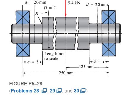
Chapter 5, Problem 28P
The shaft shown in Figure P5−28is supported by bearings at each end, which have bores of 20.0 mm. Design the shaft to carry the given load if it is steady and the shaft is stationary. Make the dimension a as large as possible while keeping the stress safe. Determine the required diameter in the middle portion. The maximum fillet permissible is 2.0 mm. Use SAE 1137 cold-drawn steel. Use a design factor of 3.
Expert Solution & Answer
Want to see the full answer?
Check out a sample textbook solution
Students have asked these similar questions
4.
A tube composed of a wrought aluminum alloy 6061-T6 is designed to transmit a torque in a
control mechanism; however the compressive stress in the tube must not exceed 7000 psi to
prevent the tube from buckling. The tube has an outside diameter of 1.25 in., a wall thickness of
0.065 in. and total length of 2.0 ft. Find the maximum torque which can be applied and the angle
of twist over the length of the tube at the maximum torque.
The figure shows a shaft mounted in bearings at A and D and having pulleys at B and C. The
forces shown acting on the pulley surfaces represent the belt tensions. The shaft is to be made of
ASTM grade 25 cast iron using a design factor na = 2.8. What diameter should be used for the
shaft?
6-in D.
300 lbf
27 lbf
360 lbf D
6 in
A
8 in
50 lbf
B
8-in D.
8 in
A gear transmits 560 N of torque to a circular shaft having a diameter of 58 mm. A
square key 13 mm on a side connects the shaft to the hub of the gear, as shown in the
figure below. The key is made from SAE 1020 cold-drawn steel. Determine the required
length of the key, L, to be safe for shear and bearing. Use a design factor of 2.0 based
on yield for shear and the AISC allowable bearing stress.
Shear
plane
Hub
Shaft
Key
Shear area = A, =b x L
Chapter 5 Solutions
Machine Elements in Mechanical Design (6th Edition) (What's New in Trades & Technology)
Ch. 5 - A link in a mechanism is made from a round bar...Ch. 5 - A link in a packaging machine mechanism has a...Ch. 5 - A cantilevered boom is part of an assembly machine...Ch. 5 - For Problems1014, use the method outlined in...Ch. 5 - For Problems1014, use the method outlined in...Ch. 5 - Figure P524shows a hydraulic cylinder that pushes...Ch. 5 - The shaft shown in Figure P528is supported by...Ch. 5 - An aluminum rod, made from alloy 6061-T6, is made...Ch. 5 - A circular bar of SAE 4140 OQT 1000 steel steps...Ch. 5 - Compute the torsional shear stress in a circular...
Knowledge Booster


Learn more about
Need a deep-dive on the concept behind this application? Look no further. Learn more about this topic, mechanical-engineering and related others by exploring similar questions and additional content below.Similar questions
- Required information A rotating shaft of 25-mm diameter is simply supported by bearing reaction forces R₁ and R₂. The shaft is loaded with a transverse load of 13 kN as shown in the figure. The shaft is made from AISI 1045 hot-rolled steel. The surface has been machined. NOTE: This is a multi-part question. Once an answer is submitted, you will be unable to return to this part. 25 mm- R₁ 200 mm- 13 KN Not to scale. -50 mm. B₂ Determine the minimum static factor of safety based on yielding. The minimum static factor of safety based on yielding isarrow_forward4) Ball bearings support the rotating axle shown below at points A and D. The rotating axle is loaded by a stationary (non-rotating) force of F = 6.8 kN. In the drawing below, all dimensions are in mm, and all geometry changes (steps in the diameter shaft) have a fillet radius of 3 mm. The axle is machined from AISI cold-drawn steel with an ultimate strength of S_u = 690 MPa and a yield strength of S_y= 580 MPa. Calculate the safety factor at the 6.8 kN load and points B and C, which experience moderate bending moments with a geometric feature that causes a stress concentration. Determine the number of cycles to failure of this part. 30 -10 -250 32 B 6.8 KN 75 -38 100- с 125 10 35 D 30arrow_forwardRequired Information A rotating shaft of 25-mm diameter is simply supported by bearing reaction forces Rjand R2. The shaft Is loaded with a transverse load of 13 kN as shown in the figure. The shaft is made from AISI 1045 hot-rolled steel. The surface has been machined. NOTE: This is a multi-part question. Once an answer is submitted, you will be unable to return to this part. 200 mm 25 mm 13 kN 50 mm- Not to scale Determine the endurance limit, adjusted as necessary with Marin factors. The endurance limit is 210.7 MPa.arrow_forward
- Problem 2: F = 10 kip -10 in- -5 in- -5 in- d/5 R. R1 d/ 10 R. 1.4 d- R2 I in The shaft shown above rotates at 1200 RPM and supports a 10 kip load. The material of the shaft is 1095 hot-rolled steel and its surface is machined and then polished. Using a factor of safety of 1.6, specify the minimum value of diameter d for a life of 1,000 hours.arrow_forward1) Ball bearings support the rotating axle shown below at points A and D. The rotating axle is loaded by a stationary (non-rotating) force of F = 6.8 kN. In the drawing below, all dimensions are in mm. While the real part has fillets (r=3mm), you can assume an abrupt change in geometry for each shaft step for this problem. The axle is machined from AISI cold-drawn steel with an ultimate strength of S_u = 690 MPa, a yield strength of S_y=580 MPa, and a modulus of Elasticity of E_steel = 207 GPa. Determine the displacement at the 6.8 kN load and points B and C. 6.8 KN 30 10 250 32 B 75 38 100 10-1 -35 30arrow_forwardPROBLEM: A shaft supported at the ends carries a spur gear and is to transmit 10 kW at 200 rpm. The weight of the gear is 1 kN. If the allowable shear stress is 45 MPa, determine the shaft diameter. FIGURE: Bearing 150 mm 100 mm. 200 mm. Gear Shaft 100 mm Bearing SOLUTION: Instructions: Solve the diameter of the shaft. To add an equation in Word, select Insert > Equation or press Alt + = Example: = F Aarrow_forward
- Problem 2: Let FA=100 N and F= 208.33 N for the shaft below. The bearings D and B act as pin supports. The shaft is made of 2014 aluminum alloy with a yield strength of 276 MPa. The shaft has a diameter of 8 mm. Based on the maximum shear stress (MSS) theory, determine if the shaft is safe. Determine the corresponding safety factor. Y 45 mm 30 mm D. 20 mm FC 20° Gear 1 50-mm dia. Shaft FA 20° Gear 2 24-mm dia.arrow_forward4. A solid square rod is cantilevered at one end. The rod is 0.6 m long and supports a completely reversing transverse load at the other end of ±2 kN. The material is AISI 1080 hot-rolled steel. If the rod must support this load for 104 cycles with a design factor of 1.5, what dimension should the square cross section have? Neglect any stress concentrations at the support end. 65arrow_forwardA stepped shaft has dimensions of D = 2 in., d = 1 in., and r= 0.1 in. It is machined from AISI steel of 200 Bhn hardness. The load is fully reversed axial torsion. 30 seconds of time history of the nominal torsional stress in the 1 in, section of the shaft, Tnom(t) = Tr/J, is shown (dots indicate the beginning/end of each load cycle; there are 20 cycles total in 30 seconds.). This duty cycle continues repeating. (a) Use Miner's rule to estimate the life of the shaft in cycles. (b) What is the expected life in hours. Su 0.5HB for steel. 30 20 10 -10 -20 -30 30 seconds D=2 in. d=1 in. f= 0.1 in. 200 Bhnarrow_forward
- Problem 4: A cast iron shaft, ASTM-25 with an ultimate tensile strength of 25,000 psi, is subjected to a tor- sional load which is completely reversed. The load is to be applied an indefinite number of cycles. The shaft is 2" in diameter and is joined to a 3" diameter shaft with a " radius fillet. The factor of safety is to be 2. What is the maximum torque that can be applied to the shaft? Solve by two methods: (1) using Soderberg's equation, (2) using s = Tc/J directly.arrow_forwardA shaft is designed to transmit power of 100 kW at 180 rpm. The allowable shear stress is 50MPa and modulus of rigidity of 80 GPa. The angle of twist is not to exceed to 1° in 4-meter length A. Calculate the diameter of the shaft in inches. B.If the shaft in A is to be fitted to a hub with material SAE 0105 and fit classification of FN3, what will be the maximum and minimum stresses based on the interference of metal.arrow_forwardUse the general shaft layout given and determine the critical diameters of the shaft based on infinite fatigue life with a design factor of 1.5. Check for yielding. Check the slopes at the bearings for satisfaction of the recommended limits in Table 7-2. Assume that the deflections for the pulleys are not likely to be critical. The material selected is 1050 Q and T. Given: Sut = 163 kpsi and Sy = 117 kpsi. Use the following shaft layout assuming a gear transmits torque through a key and keyseat at location A to another gear at location B. 16 in 14 in F3 9 in Gear A 20-in dia. Gear B 8-in dia. FA 300 lbf 20 A) Determine the location of the critical section on the shaft. B) If the shaft's loading is fully reversed and the torque between points A and B is constant, what are the values of the mean and alternating torques and the mean and alternating moments in lbf-in?arrow_forward
arrow_back_ios
SEE MORE QUESTIONS
arrow_forward_ios
Recommended textbooks for you
 Elements Of ElectromagneticsMechanical EngineeringISBN:9780190698614Author:Sadiku, Matthew N. O.Publisher:Oxford University Press
 Mechanics of Materials (10th Edition)Mechanical EngineeringISBN:9780134319650Author:Russell C. HibbelerPublisher:PEARSON
 Thermodynamics: An Engineering ApproachMechanical EngineeringISBN:9781259822674Author:Yunus A. Cengel Dr., Michael A. BolesPublisher:McGraw-Hill Education
 Control Systems EngineeringMechanical EngineeringISBN:9781118170519Author:Norman S. NisePublisher:WILEY
 Mechanics of Materials (MindTap Course List)Mechanical EngineeringISBN:9781337093347Author:Barry J. Goodno, James M. GerePublisher:Cengage Learning
 Engineering Mechanics: StaticsMechanical EngineeringISBN:9781118807330Author:James L. Meriam, L. G. Kraige, J. N. BoltonPublisher:WILEY
Elements Of Electromagnetics
Mechanical Engineering
ISBN:9780190698614
Author:Sadiku, Matthew N. O.
Publisher:Oxford University Press
Mechanics of Materials (10th Edition)
Mechanical Engineering
ISBN:9780134319650
Author:Russell C. Hibbeler
Publisher:PEARSON
Thermodynamics: An Engineering Approach
Mechanical Engineering
ISBN:9781259822674
Author:Yunus A. Cengel Dr., Michael A. Boles
Publisher:McGraw-Hill Education
Control Systems Engineering
Mechanical Engineering
ISBN:9781118170519
Author:Norman S. Nise
Publisher:WILEY
Mechanics of Materials (MindTap Course List)
Mechanical Engineering
ISBN:9781337093347
Author:Barry J. Goodno, James M. Gere
Publisher:Cengage Learning
Engineering Mechanics: Statics
Mechanical Engineering
ISBN:9781118807330
Author:James L. Meriam, L. G. Kraige, J. N. Bolton
Publisher:WILEY
Fluid Mechanics - Viscosity and Shear Strain Rate in 9 Minutes!; Author: Less Boring Lectures;https://www.youtube.com/watch?v=_0aaRDAdPTY;License: Standard youtube license