
Machine Elements in Mechanical Design (6th Edition) (What's New in Trades & Technology)
6th Edition
ISBN: 9780134441184
Author: Robert L. Mott, Edward M. Vavrek, Jyhwen Wang
Publisher: PEARSON
expand_more
expand_more
format_list_bulleted
Concept explainers
Videos
Textbook Question
Chapter 5, Problem 24P
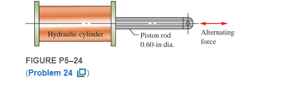
Figure P5−24shows a hydraulic cylinder that pushes a heavy tool during the outward stroke, placing a compressive load of 400 lb in the piston rod. During the return stroke, the rod pulls on the tool with a force of 1500 lb. Compute the resulting design factor for the 0.60-in-diameter rod when subjected to this pattern of forces for many cycles. The material is SAE 4130 WQT 1300 steel. If the resulting design factor is much different from 4.0, determine the size of the rod that would produce
Expert Solution & Answer
Want to see the full answer?
Check out a sample textbook solution
Students have asked these similar questions
Figure P5-24 shows a hydraulic cylinder that pushes a heavy tool during the outward stroke, placing a compressive load of 400 lb in the piston rod. During the return stroke, the rod pulls on the tool with a force of 1500 lb. Compute the resulting design factor for the .60 in diameter rod when subjected to this pattern of forces for many cycles. The material is AISI 4130 WQT 1300 steel. If the resulting design factor is much different from 4.0, determine the size of rod that would produce N=4.0
Condition #1:
A structural support for a machine is subjected to a static compression load of 20 kN. The support is
manufactured from a circular rod made from SAE 1040 Hot Rolled steel. Specify suitable diameter for
the cross section of the rod based on the basic size. Steel data are available in Table A-10 from the
textbook.
Condition #2:
The same structural support of the basic size determined in Condition 1 is subjected to a tensile load of
15 kN that is repeated several thousand times over the life of the machine. This load is not an addition to
the 20 kN. Specify a suitable steel that is suitable to this application based on the basic size determined in
Condition #1. Loading of Condition #1 does not apply here.
Condition #3:
The same structural support from Condition 2 is heated from room temperature of 25°C. The support is
placed inside a frame on both ends. There is a total clearance of 0.2 mm between the support and its
frame. Initial length of the rod is 200 mm. Specify the…
The C-clamp in Figure P10–9 is made of cast zinc, ZA12. Determine the allowable clamping force that the clamp can exert if it is desired to have a design factor of 4 based on ultimate strength in either tension or compression.
Chapter 5 Solutions
Machine Elements in Mechanical Design (6th Edition) (What's New in Trades & Technology)
Ch. 5 - A link in a mechanism is made from a round bar...Ch. 5 - A link in a packaging machine mechanism has a...Ch. 5 - A cantilevered boom is part of an assembly machine...Ch. 5 - For Problems1014, use the method outlined in...Ch. 5 - For Problems1014, use the method outlined in...Ch. 5 - Figure P524shows a hydraulic cylinder that pushes...Ch. 5 - The shaft shown in Figure P528is supported by...Ch. 5 - An aluminum rod, made from alloy 6061-T6, is made...Ch. 5 - A circular bar of SAE 4140 OQT 1000 steel steps...Ch. 5 - Compute the torsional shear stress in a circular...
Knowledge Booster


Learn more about
Need a deep-dive on the concept behind this application? Look no further. Learn more about this topic, mechanical-engineering and related others by exploring similar questions and additional content below.Similar questions
- Homework -4- Q1- Find the power required to drive a 1.5-in power screw having double square threads with a pitch of 1/4 in. The nut is to move at a velocity of 2 in/s and move a load of F = 2.2 kips. The frictional coefficients are 0.10 for the threads and 0.15 for the collar. The frictional diameter of the collar is 2.25 in.arrow_forwardA holding fixture for a workpiece 37.5 mm thick at the clamp locations is being designed. The detail of one of the clamps is shown in the figure. A spring is required to drive the clamp upward when removing the workpiece with a starting force of 45 N. The clamp screw has an M10x1.25 thread. Allow a diametral clearance of 1.25 mm between it and the uncompressed spring. It is further specified that the free length of the spring should be Lo ≤ 48 mm, the solid height L, S 31.5 mm, and the safety factor when closed solid should be n, 21.2. Starting with d=2 mm, design a suitable helical coil compression spring for this fixture. For A227 HD steel, wire diameters are available in 0.2-mm increments between 0.2 to 3.2 mm. Spherical washer Slot Workpiece - Clamp screw AAAAAA Clamp Groove Pinarrow_forwardA structural support for a machine is subjected to a static compression load of 20 kN. The support is manufactured from a circular rod made from SAE 1040 Hot Rolled steel. Specify suitable diameter for the cross section of the rod based on the basic size. Steel data are available in Table A-10 from the textbook.arrow_forward
- QI: A double-threaded 30-mm power screw is 30 mm in diameter with a pitch of 6 mm. The coefficients of friction are 0.05 for the collar and 0.08 for the threads. The frictional diameter of the collar is 40 mm. if Tg=18 N.m: 1- Find the A vertical load on the screw, the torque used to lower the load and screw efficiency. 2- Compute all the stresses on the screw body that will cause by the load.arrow_forwardA 750 mm steel pulley transmits 120 hp at 700 rpm. The arc of contact between the belt and pulley is 152 degrees, the coefficient of friction between belt and pulley is 0.30 and the safe working stress of the belt is 2.0 MPa. Find the width of the belt used in mm if its thickness is 20 mm.arrow_forwardThe shaft in Figure P12–2 rotates at 200 rpm. Pulley A receives 10 hp from below. Gear C delivers 6 hp to the mating gear below it. Chain sprocket D delivers 4 hp to a shaft above. Use SAE 1117 cold-drawn steel. Find: (a) Determine the magnitude of the torque in the shaft at all points. (b) Compute the forces acting on the shaft at all powertransmitting elements. (c) Compute the reactions at the bearings.arrow_forward
- L21. Figure P4-21 shows an anvil for an impact hammer held in a fixture by a circular pin. If the force is to be 500 lb, specify a suitable diameter for the steel pin if it is to be made from SAE 1040 WQT 900. 4-21arrow_forwardCompute the design factor in the middle portion only of the rod AC if the steady vertical force on the boom is 2500 lb. The rod is rectangular, 1.50 in by 3.50 in, and is made from SAE 1144 cold-drawn steel. Include a mohr circle.arrow_forwardA link in a mechanism is to be subjected to a tensile force that varies from 3500 to 500 N in a cyclical fashion as the mechanism runs. It has been decided to use AISI 1040 cold-drawn steel. Complete the design of the link, specifying a suitable cross-sectional shape and dimensions.arrow_forward
- 6. A circular bar is to carry a fluctuating torque from 25 to 55 N-m. Use AISI C1144 OQT 1000for the bar and compute for the required diameter for a design factor of 2. Attachmentsproduce a stress concentration of 2.5 near the ends of the bar. please also give the FBD, thank youarrow_forwardOne flange is attached to four 5x8 grade and M16 bolt connections with a total preload force of 80,000 N Calculate the factor of the boltarrow_forwardFigure P10–27 shows a crank to which a force f of 1200 N is applied. Compute the maximum stress in the circular portion of the crank.arrow_forward
arrow_back_ios
SEE MORE QUESTIONS
arrow_forward_ios
Recommended textbooks for you
 Elements Of ElectromagneticsMechanical EngineeringISBN:9780190698614Author:Sadiku, Matthew N. O.Publisher:Oxford University Press
 Mechanics of Materials (10th Edition)Mechanical EngineeringISBN:9780134319650Author:Russell C. HibbelerPublisher:PEARSON
 Thermodynamics: An Engineering ApproachMechanical EngineeringISBN:9781259822674Author:Yunus A. Cengel Dr., Michael A. BolesPublisher:McGraw-Hill Education
 Control Systems EngineeringMechanical EngineeringISBN:9781118170519Author:Norman S. NisePublisher:WILEY
 Mechanics of Materials (MindTap Course List)Mechanical EngineeringISBN:9781337093347Author:Barry J. Goodno, James M. GerePublisher:Cengage Learning
 Engineering Mechanics: StaticsMechanical EngineeringISBN:9781118807330Author:James L. Meriam, L. G. Kraige, J. N. BoltonPublisher:WILEY
Elements Of Electromagnetics
Mechanical Engineering
ISBN:9780190698614
Author:Sadiku, Matthew N. O.
Publisher:Oxford University Press
Mechanics of Materials (10th Edition)
Mechanical Engineering
ISBN:9780134319650
Author:Russell C. Hibbeler
Publisher:PEARSON
Thermodynamics: An Engineering Approach
Mechanical Engineering
ISBN:9781259822674
Author:Yunus A. Cengel Dr., Michael A. Boles
Publisher:McGraw-Hill Education
Control Systems Engineering
Mechanical Engineering
ISBN:9781118170519
Author:Norman S. Nise
Publisher:WILEY
Mechanics of Materials (MindTap Course List)
Mechanical Engineering
ISBN:9781337093347
Author:Barry J. Goodno, James M. Gere
Publisher:Cengage Learning
Engineering Mechanics: Statics
Mechanical Engineering
ISBN:9781118807330
Author:James L. Meriam, L. G. Kraige, J. N. Bolton
Publisher:WILEY
Stresses Due to Fluctuating Loads Introduction - Design Against Fluctuating Loads - Machine Design 1; Author: Ekeeda;https://www.youtube.com/watch?v=3FBmQXfP_eE;License: Standard Youtube License