
Concept explainers
Videos
A link in a
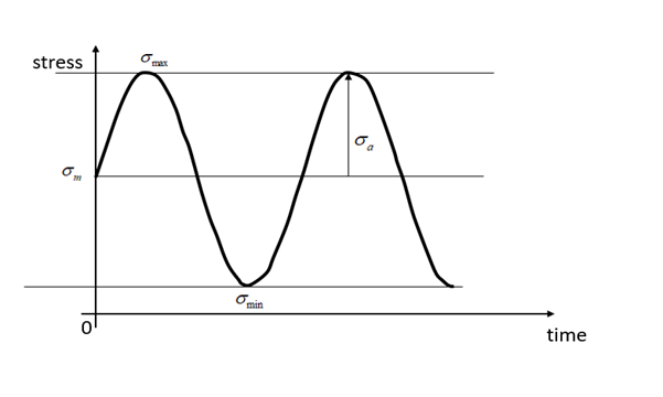
The minimum stress, maximum stress, mean stress, stress ratio, and alternating stress.
Answer to Problem 1P
Maximum stress is 44.6 MPa
Minimum stress is 6.37 MPa
Mean stress is 25.5 MPa
Alternating stress = 19.11 MPa
Stress ratio is 0.143
Explanation of Solution
Given Information:
Diameter of the bar, D = 10 mm
Maximum tensile force =
Minimum tensile force =
Area of the bar, A
Stress in the bar is defined as,
For maximum stress,
For minimum stress,
Mean stress,
Alternating stress,
Stress Ratio, R
Stress vs time plot
Want to see more full solutions like this?
Chapter 5 Solutions
Machine Elements in Mechanical Design (6th Edition) (What's New in Trades & Technology)


- Please solve ellaborately and include the untis in every step, show diagram and write your solutions clearly and readable if your solution is in written form. Your work will be appreaciated much. Thank You! A pulley 600 mm. in diameter transmits 40 kW at 500 rpm. The arc of contact between thebelt and pulley is 144° having a center distance of 1100 mm. Determine: (a) diameter ofthe driven pulley for open belt drive, (b) speed of the driven pulley, and (c) belt length foropen belt connection.arrow_forwardThe figure below is a schematic drawing of a shaft that supports two V-belt pulleys. The loose belt tension on the pulley at A is 15% of the tension on the tight side. The shaft material has a yield strength of 300 MPa and an ultimate tensile strength of 520 MPa. Calculate the shaft diameter.arrow_forwardTwo 400 mm diameter pulley are keyed to a simply supported shaft 500mm apart. Each pulley is 100 mm from its support and has horizontal belts, tension ratio being 2.5. If the shear stress is to be limited to 80MPa while transmitting 45 kW at 900 rpm. Find the shaft if it is to be used for the input - output belts being on the same or opposite sides.arrow_forward
- A 600 mm steel pulley transmits 50 kW at 900 rpm. The arc of contact between the belt and pulley is 144 degrees, the coefficient of friction between belt and pulley is 0.3 and the safe working stress of the belt is 2750 kPa. Find the width of the belt used if the thickness is equal to 12 mm.arrow_forwardPlease solve ellaborately and include the untis in every step, show diagram and write your solutions clearly and readable if your solution is in written form. Your work will be appreaciated much. Thank You. A pulley 190 mm. in diameter transmits 22 kW at 350 rpm. The arc of contact between the belt and pulley is 115.7° having a center distance of 410 mm. Determine (a) diameter of the driven pulley for open belt drive,(b) speed of the driven pulley, and (c) belt length for an open belt connection. (a) Diameter of Driven Pulley Answer and unit for part 1 (b) Speed of the Driven Pulley Answer and unit for part 2 (c) Belt Lengtharrow_forwardPulleys A and B are separated by 450 mm. The shaft has a diameter of 40 mm and is made of steel with G=75GPa�=75GPa. Pulley A has a radius of 100 mm and pulley b has a radius of 150 mm. The belt on pulley A has a tension of 4 kN in the counter-clockwise direction and a tension of 10 kN in the clockwise direction. The belt on pulley B has a tension of 6 kN in the counter-clockwise direction and a tension of 2 kN in the clockwise direction. What is the angle of twist (in degrees) of pulley B relative to pulley A?arrow_forward
- (3) A single-threaded jackscrew has square threads. The screw diameter is l in. and there are 4 threads/in. A friction collar has a 2-in. outside diameter and an l-in. inside diameter. The coefficient of friction is 0.1 for the collar and 0.15 for the threads. How much force must be applied on a l2-in. (radius) jack lever to raise a load of 1,000lb?arrow_forwardOne flange is attached to four 5x8 grade and M16 bolt connections with a total preload force of 80,000 N Calculate the factor of the boltarrow_forwardSymmetrical shoes will not create moment around the joint The position of the pads with an angle of 90° on the brake where it is placed in the figure is shown in the figure. The brake mechanism is fixed to the ground by the support plate. The disc in the figure rotates clockwise and the friction coefficient of the pads is accepted as 0.491. If a force of 565 N is applied on the arm from the point shown on the figure;a) What is the dimension e shown in the figure so that the shoe does not create a moment around the joint?how much should it be? Calculate.b) Draw free body diagrams of ABC opening lever and both lining levers.c) What is the normal force acting on each pad? How much braking torqueoccurs? calculatearrow_forward
- An oval profile straightening machine is shown in the adjacent figure. The movement bolt in the mechanism is single-ended, 80mm diameter and 10mm. It has a square screw with a step. Tightening the movement bolt to the profile An axial force of 10 kN is required as a force. The average diameter between the handle and the bolt is 60 mm. with bolt The friction coefficient between the nut and bolt and the handle is 0.12. The length of the force arm is given as 500 mm. i) Applying the bolt to the lever to apply the desired axial load Find the required force. ii) Find the efficiency of the mechanism. iii) Checking the bolt's security taking into account the A-A cross-section Please pay. Yield strength of bolt Syield strenght= 420 MPaarrow_forward3. Design a compression coupling for a shaft to transmit 1300 N-m. The allowable shear stress for the shaft and key is 40 MPa and the number of bolts connecting the two halves are 4. The permissible tensile stress for the bolts material is 70 MPa. The coefficient of friction between the muff and the shaft surface may be taken as 0.3.arrow_forwardFind the Axial Forces in members 1 - 5. Find the Displacement Displacement of joint A (mm, positive right and up) for both Horizontal and Verticalarrow_forward
 Mechanics of Materials (MindTap Course List)Mechanical EngineeringISBN:9781337093347Author:Barry J. Goodno, James M. GerePublisher:Cengage Learning