Videos
Referring to the semiconductor processing tool of Problem 5.13, it is desired at some point in the manufacturing cycle to cool the chuck, which is made of aluminum alloy 2024. The proposed cooling scheme passes air at 20°C between the air-supply head and the chuck surface.
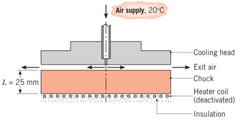
(a) If the chuck is initially at a uniform temperature of l00°C, calculate the time required for its lower surface to reach 25°C, assuming a uniform convection coefficient of 50 W/m2⋅K at the head—chuck interface.
(b) Generate a plot of the time-to-cool as a function of the convection coefficient for the range 10≤h≤2000 W/m2⋅K. If the lower limit represents a free convection condition without any head present, comment on the effectiveness of the head design as a method for cooling the chuck.
Want to see the full answer?
Check out a sample textbook solution
Chapter 3 Solutions
Introduction to Heat Transfer


- Auto Controls (a) Refer to the above figure .What kind of controller is it ? (b) simplify the block diagramto derive the closed loop transfer function of the system. (C) What are the assumptions thatare needed to make to findthe controller gain ? What arethe value of Kp , Ti and Td ?arrow_forwardAuto Controls Design a PID controller for thefollowing system so that the modified system satisfies the followingspecifications : 1. settling time ,ts = 1.96 s and % Overshoot Mp = 70.7 % Assume a non-dominant pole at s = -15 to solve the problem The plot the compensated andThen plot the uncompensated system in MATLAB. what can you see from the plot ? what is your observation ?arrow_forwardFourth year Monthly exam\3 2024-2025 Power plant Time: 1 Hr Q1. A gas turbine power plant operates on a modified Brayton cycle consisting of two-stage compression with intercooling to the initial temperature between stages, two-stage expansion with reheating to the maximum cycle temperature, and two regenerative heat exchangers. The following data is given: Inlet air temperature: 300 K Maximum cycle temperature: 1400 K Pressure ratio across each compressor stage: 4 Pressure ratio across each turbine stage: 4 Isentropic efficiency of compressors and turbines: 85% Effectiveness of each regenerator: 80% a) Draw a schematic and T-s diagram of the cycle. b) Determine the thermal efficiency of the cycle. c) Calculate the net specific work output (in kJ/kg). d) Discuss the impact of regenerators on the cycle performance. Examiner Prof. Dr. Adil Al-Kumaitarrow_forward
- Auto Controls The figure is a schematic diagram of an aircraft elevator control system. The input to the systemin the deflection angle of the control lever , and the output is the elevator angle phi.show that for each angle theta of the control lever ,there is a corresponding elevator angle phi. Then find Y(s)/theta(s) and simplify the resulting transfer function . Also note from the diagram that y and phi is relatedarrow_forwardLiquid hexane flows through a counter flow heat exchanger at 5 m3/h as shown in Figure E5.5.The hexane enters the heat exchanger at 90°C. Water, flowing at 5 m3/h, is used to cool the hexane.The water enters the heat exchanger at 15°C. The UA product of the heat exchanger is found to be2.7 kW/K. Determine the outlet temperatures of the hot and cold fluids and the heat transfer ratebetween them using LMTD method.arrow_forwardDetermine the fluid outlet temperatures and the heat transfer rate for the counter flow heatexchanger described in Problem 3 using the ε-NTU model. Assume that the properties can beevaluated at the given fluid inlet temperatures.arrow_forward
- Section View - practice Homework 0.5000 3.0000 2,0000 1.0000arrow_forwardDrawing the section view for the following multiview drawing AutoCAD you see the section pratice I need to show how to autocadarrow_forwardA boiler with 80% efficiency produces steam at 40bar and 500 C at a rate of 1.128kg/s. The temperature of the feed water is raised from 25 C to 125 C in the economizer and the ambient air is drawn to the boiler at a rate of 2.70 kg/s at 16 C. The flue gases leave the chimney at rate of 3 kg/s at 150 C with specific heat of 1.01 kJ/kg.K. The dryness fraction of steam collected in the steam drum is 0.95. 1- Determine the heat value of the fuel. 2- The equivalence evaporation. 3- Draw the heat balance sheet.arrow_forward
- A rotating shaft is made of 42 mm by 4 mm thick cold-drawn round steel tubing and has a 6 mm diameter hole drilled transversely through it. The shaft is subjected to a pulsating torque fluctuating from 20 to 160 Nm and a completely reversed bending moment of 200 Nm. The steel tubing has a minimum strength of Sut = 410 MPa (60 ksi). The static stress-concentration factor for the hole is 2.4 for bending and 1.9 for torsion. The maximum operating temperature is 400˚C and a reliability of 99.9% is to be assumed. Find the factor of safety for infinite life using the modified Goodman failure criterion.arrow_forwardI need help with a MATLAB code. This code just keeps running and does not give me any plots. I even reduced the tolerance from 1e-9 to 1e-6. Can you help me fix this? Please make sure your solution runs. % Initial Conditions rev = 0:0.001:2; g1 = deg2rad(1); g2 = deg2rad(3); g3 = deg2rad(6); g4 = deg2rad(30); g0 = deg2rad(0); Z0 = 0; w0 = [0; Z0*cos(g0); -Z0*sin(g0)]; Z1 = 5; w1 = [0; Z1*cos(g1); -Z1*sin(g1)]; Z2 = 11; w2 = [0; Z2*cos(g2); -Z2*sin(g2)]; [v3, psi3, eta3] = Nut_angle(Z2, g2, w2); plot(v3, psi3) function dwedt = K_DDE(~, w_en) % Extracting the initial condtions to a variable % Extracting the initial condtions to a variable w = w_en(1:3); e = w_en(4:7); Z = w_en(8); I = 0.060214; J = 0.015707; x = (J/I) - 1; y = Z - 1; s = Z; % Kinematic Differential Equations dedt = zeros(4,1); dedt(1) = pi*(e(3)*(s-w(2)-1) + e(2)*w(3) + e(4)*w(1)); dedt(2) = pi*(e(4)*(w(2)-1-s) + e(3)*w(1) - e(1)*w(3)); dedt(3) = pi*(-e(1)*(s-w(2)-1) - e(2)*w(1) + e(4)*w(3));…arrow_forwardalpha 1 is not zero alpha 1 can equal alpha 2 use velocity triangle to solve for alpha 1 USE MATLAB ONLY provide typed code solve for velocity triangle and dont provide copied answer Turbomachienery . GIven: vx = 185 m/s, flow angle = 60 degrees, (leaving a stator in axial flow) R = 0.5, U = 150 m/s, b2 = -a3, a2 = -b3 Find: velocity triangle , a. magnitude of abs vel leaving rotor (m/s) b. flow absolute angles (a1, a2, a3) 3. flow rel angles (b2, b3) d. specific work done e. use code to draw vel. diagram Use this code for plot % plots Velocity Tri. in Ch4 function plotveltri(al1,al2,al3,b2,b3) S1L = [0 1]; V1x = [0 0]; V1s = [0 1*tand(al3)]; S2L = [2 3]; V2x = [0 0]; V2s = [0 1*tand(al2)]; W2s = [0 1*tand(b2)]; U2x = [3 3]; U2y = [1*tand(b2) 1*tand(al2)]; S3L = [4 5]; V3x = [0 0]; V3r = [0 1*tand(al3)]; W3r = [0 1*tand(b3)]; U3x = [5 5]; U3y = [1*tand(b3) 1*tand(al3)]; plot(S1L,V1x,'k',S1L,V1s,'r',... S2L,V2x,'k',S2L,V2s,'r',S2L,W2s,'b',U2x,U2y,'g',...…arrow_forward
 Principles of Heat Transfer (Activate Learning wi...Mechanical EngineeringISBN:9781305387102Author:Kreith, Frank; Manglik, Raj M.Publisher:Cengage Learning