
Electrical Engineering: Principles & Applications (7th Edition)
7th Edition
ISBN: 9780134484143
Author: Allan R. Hambley
Publisher: PEARSON
expand_more
expand_more
format_list_bulleted
Concept explainers
Videos
Textbook Question
Chapter 2, Problem 2.53P
Given
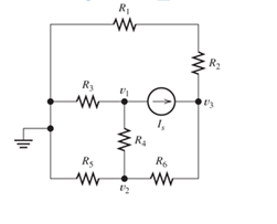
Figure P2.53
Expert Solution & Answer

Trending nowThis is a popular solution!

Students have asked these similar questions
Consider the circuit shown in below Figure, Find values of the resistances R1 and R2 that cause the
voltages v1 and v2 to be v1 = 1 V and v2 = 2 V.
500 2
+
+
R1
R2
() 5 mA
3 mA
V1
V2
6:03 PM
50°F Clear
2/18/2022
P Type here to search
Del
End
F10
PgUp.
F11
PgDn
F12
PrtScn
Home
F7
F2
F3
F1
&
)
Backspace
%23
%24
%
4.
5
7
8.
9.
2
3
W.
Design a circuit that will have an outcome of the highest equivalent resistance across the terminals with a 30Vdc source. Given that the R1 = 10 R2 = 50 R3 = 85. Determine the equivalent resistance from the combination of resistors, R123, R12, R23, and R1.
For R1=50, R2=60, R3=40, R4=10, R5=40, V1=45 V, V2=30 V & I1=9 A in the circuit shown below, apply
source transformation to find Vx (in volt)
V1
R1
Oa. -28.405797101449
Ob. 14.202898550725
Oc. -14.202898550725
Od. -42.608695652174
where V =
R3
ww
V
R2
where R =
R5
The circuit after source transformation will be as follows:
R3
R4
V2
The circuit after source transformation will be as follows:
R3
ww
Chapter 2 Solutions
Electrical Engineering: Principles & Applications (7th Edition)
Ch. 2 - Reduce each of the networks shown in Figure P2.1...Ch. 2 - A 4- resistance is in series with the parallel...Ch. 2 - Find the equivalent resistance looking into...Ch. 2 - Suppose that we need a resistance of 1.5 k and...Ch. 2 - Find the equivalent resistance between terminals a...Ch. 2 - Find the equivalent resistance between terminals a...Ch. 2 - What resistance in parallel with 120 results in...Ch. 2 - Determine the resistance between terminals a and b...Ch. 2 - Two resistances having values of R and 2R are in...Ch. 2 - A network connected between terminals a and b...
Ch. 2 - Two resistances R1 and R2 are connected in...Ch. 2 - Find the equivalent resistance for the infinite...Ch. 2 - If we connect n 1000- resistances in parallel,...Ch. 2 - The heating element of an electric cook top has...Ch. 2 - We are designing an electric space heater to...Ch. 2 - Sometimes, we can use symmetry considerations to...Ch. 2 - The equivalent resistance between terminals a and...Ch. 2 - Three conductances G1 G2, and G3 are in series....Ch. 2 - Most sources of electrical power behave as...Ch. 2 - The resistance for the network shown in Figure...Ch. 2 - Often, we encounter delta-connected loads such as...Ch. 2 - What are the steps in solving a circuit by network...Ch. 2 - Find the values of i1 and i2 in Figure P2.23....Ch. 2 - Find the voltages v1 and v2 for the circuit shown...Ch. 2 - Find the values of v and i in Figure P2.25. Figure...Ch. 2 - Consider the circuit shown in Figure P2.24....Ch. 2 - Find the voltage v and the currents i1 and 12 for...Ch. 2 - Find the values of vs, v1, and i2 in Figure P2.28....Ch. 2 - Find the values of i1 and i2 in Figure P2.29....Ch. 2 - Consider the cirrcuit shown in Figure P2.30 Find...Ch. 2 - Solve for the values of i1, i2, and the powers for...Ch. 2 - The 12-V source in Figure P2.32 is delivering 36...Ch. 2 - Refer to the circuit shown in Figure P2.33. With...Ch. 2 - Find the values of i1 and i2 in Figure P2.34. Find...Ch. 2 - Find the values of i1 and i2 in Figure P2.35...Ch. 2 - Use the voltage-division principle to calculate...Ch. 2 - Use the current-division principle to calculate i1...Ch. 2 - Use the voltage-division principle to calculate...Ch. 2 - Use the current-division principle to calculate...Ch. 2 - Suppose we need to design a voltage-divider...Ch. 2 - A source supplies 120 V to the series combination...Ch. 2 - We have a 60- resistance, a 20- resistance, and...Ch. 2 - A worker is standing on a wet concrete floor,...Ch. 2 - Suppose we have a load that absorbs power and...Ch. 2 - We have a load resistance of 50 that we wish to...Ch. 2 - We have a load resistance of 1 k that we wish to...Ch. 2 - The circuit of Figure P2.47 is similar to networks...Ch. 2 - Write equations and solve for the node voltages...Ch. 2 - Solve for the node voltages shown in Figure P2.49....Ch. 2 - Solve for the node voltages shown in Figure P2.50....Ch. 2 - Given R1=4 , R2=5 , R2=8 , R4=10 , R5=2 , and...Ch. 2 - Determine the value of i1 in Figure P2.52 using...Ch. 2 - Given R1=15 , R5=5 , R3=20 , R4=10 , R5=8 , R6=4 ,...Ch. 2 - In solving a network, what rule must you observe...Ch. 2 - Use the symbolic features of MATLAB to find an...Ch. 2 - Solve for the values of the node voltages shown in...Ch. 2 - Solve for the node voltages shown in Figure P2.57....Ch. 2 - Solve for the power delivered to the 8- ...Ch. 2 - Solve for the node voltages shown in Figure P2.59....Ch. 2 - Find the equivalent resistance looking into...Ch. 2 - Find the equivalent resistance looking into...Ch. 2 - Figure P2.62 shows an unusual voltage-divider...Ch. 2 - Solve for the node voltages in the circuit of...Ch. 2 - We have a cube with 1- resistances along each...Ch. 2 - Solve for the power delivered to the 15- resistor...Ch. 2 - Determine the value of v2 and the power delivered...Ch. 2 - Use mesh-current analysis to find the value of i1...Ch. 2 - Solve for the power delivered by the voltage...Ch. 2 - Use mesh-current analysis to find the value of v...Ch. 2 - Use mesh-current analysis to find the value of i3...Ch. 2 - Use mesh-current analysis to find the values of i1...Ch. 2 - Find the power delivered by the source and the...Ch. 2 - Use mesh-current analysis to find the values of i1...Ch. 2 - Use mesh-current analysis to find the values of i1...Ch. 2 - The circuit shown in Figure P2.75 is the dc...Ch. 2 - Use MATLAB and mesh-current analysis to determine...Ch. 2 - Connect a 1-V voltage source across terminals a...Ch. 2 - Connect a 1-V voltage source across the terminals...Ch. 2 - Use MATLAB to solve for the mesh currents in...Ch. 2 - Find the Thévenin and Norton equivalent circuits...Ch. 2 - We can model a certain battery as a voltage source...Ch. 2 - Find the Thévenin and Norton equivalent circuits...Ch. 2 - Find the Thévenin and Norton equivalent circuits...Ch. 2 - Find the Thévenin arid Norton equivalent circuits...Ch. 2 - An automotive battery has an open-circuit voltage...Ch. 2 - A certain two-terminal circuit has an open-circuit...Ch. 2 - If we measure the voltage at the terminals of a...Ch. 2 - Find the Thévenin and Norton equivalent circuits...Ch. 2 - Find the maximum power that can be delivered to a...Ch. 2 - Find the maximum power that can be delivered to a...Ch. 2 - Figure P2.91 shows a resistive load RL connected...Ch. 2 - Starling from the Norton equivalent circuit with a...Ch. 2 - A battery can be modeled by a voltage source Vt in...Ch. 2 - Use superposition to find the current i in Figure...Ch. 2 - Solve for is in Figure P2.49 by using...Ch. 2 - Solve the circuit shown in Figure P2.48 by using...Ch. 2 - Solve for i1 in Figure P2.34 by using...Ch. 2 - Another method of solving the circuit of Figure...Ch. 2 - Use the method of Problem P2.98 for the circuit of...Ch. 2 - Solve for the actual value of i6 for the circuit...Ch. 2 - Device A shown in Figure P2.101 has v=3i2 for i 0...Ch. 2 - The Wheatstone bridge shown in Figure 2.66 is...Ch. 2 - The Wheatstone bridge shown in Figure 2.66has...Ch. 2 - In theory, any values can be used for R1 and R3 in...Ch. 2 - Derive expressions for the Thévenin voltage and...Ch. 2 - Derive Equation 2.93 for the bridge circuit of...Ch. 2 - Prob. 2.107PCh. 2 - Explain what would happen if, in wiring the bridge...Ch. 2 - Match each entry in Table T2.1(a) with the best...Ch. 2 - Consider the circuit of Figure T2.2 with vs=96V ,...Ch. 2 - Write MATLAB code to solve for the node voltages...Ch. 2 - Write a set of equations that can be used to solve...Ch. 2 - Determine the Thévenin and Norton equivalent...Ch. 2 - According to the superposition principle, what...Ch. 2 - Determine the equivalent resistance between...Ch. 2 - Transform the 2-A current source and 6- ...
Knowledge Booster


Learn more about
Need a deep-dive on the concept behind this application? Look no further. Learn more about this topic, electrical-engineering and related others by exploring similar questions and additional content below.Similar questions
- Determine r2 using product/sum rule. RT=40 ohms R1=200 ohms R2=? Solve using this equation "RT=(R1 X R2)/(R1+R2)" Also its a parallel circuitarrow_forwardQ2 – For the circuit shown in the Figure below, use superposition to find “v" in terms of R's and source values. U1 R1 R3 U2 R2.arrow_forwardRefer to the following circuit diagram. Find the current Is1 supplied by source E₁. and current Is2 supplied by E2. E₁ 130V Ist A Z₁ 3352 N Z₂ 1052 B D Z₁ 2402 Z 502 C Isz E₂ 110Varrow_forward
- In the circuit below, the currents through the four resistors are as indicated. Use the junction rule to write the equations representing the relationship between the currents at the point d. (Use the following as necessary: 14, 15, and 16.) R₁ www = 0 W €₁ 1₁ R₂ 1₂ R3 a 13 E4 16 15 R4 E2 E3arrow_forwardUse superposition to compute for the DC voltage levels for node B, C, and D. The dependent current source is equal to I1=hfeIb, hfe=177. What is the dc current Ib using superposition when 15V is turned on? when the 0.7V is turned on?arrow_forwardAccording to the circuit and parameters given in the figure, make your calculations and write the table. wmww w n ww bbn m w w w w Please fill in. www ww w +12V +12V M1 M2 2kN 10kN K ImA/V² 0.5mA/V² VTH 2V 1.5V 22kN M2 MODE 33k2 M1 Ip 1kN VGS Vps K1=lmA/V² Vth1=2V; M2: K2=0.5mA/V² VTH2=1.5Varrow_forward
- Represent the electrical network shown in figure in state space where Output is Vo(t), Input is vi(t) and State variables are the following below: Xi = V1 X2 = 14 X3 = Vo R2 = 1 Ohm V, R, = 1 Ohm = 1 Ohm V2 V, C, = 1F L = 1H C2 = 1 F V,arrow_forwardFinding the direction of the currents. Finding currents given that R2: 10.94 x 10^2 ohmR3: 9.89 x 10^2 ohmR4: 25 ohm Terminal Potential: Battery 1: 5 V using Kirchoff's laws. You will check some of the laws that govern electrical circuitsDirect current: conservation of current in a node, addition of potentialsfor series components, addition of currents for parallel componentsarrow_forwardYou have a voltage source of 10 V and require a voltage of 8 V for the (very largeresistance) load you would add to the circuit. Design a voltage divider to create thisoutput–draw the circuit and label all elements with their values. You do not need toinclude the load resistance. Demonstrate that your choices lead to the desired outcome(using math).arrow_forward
- the follow up question wasnt answered properly the question wasnt about the superposition theorm it was about ic1=5<60 /.... and ic2=4+j4 .... can you please explain how you got both formulas in detail? thank you.arrow_forwardM R1 11 R2 ww V2 Figure 5: A circuit R3 M R4 Ic a Given the circuit in figure 5 with component values R₁ = 60 №, R₂ = 20 N, R3 = 80 N, R4 = 40, l₁ = 4 A, V₂ = 160 lc V. The current Ic is noted on the circuit. Node a and bare denoted on the circuit. You are free to use any methods explained in class to derive the Thevenin equivalent circuit between node a and b.arrow_forwardFor the circuit shown, select the values of R1, R2 & R3 so that: y11=0.006 mho, y12 =y21=-0.001 mho & y22=0.003 mho I R2 I2 V1 R1 R3 V2 400 ohm, 500 ohm, and 200 ohm 200 ohm, 400 ohm, and 500 ohm 200 ohm, 1000 ohm, and 500 ohm 400 ohm, 1000 ohm, and 400 ohmarrow_forward
arrow_back_ios
SEE MORE QUESTIONS
arrow_forward_ios
Recommended textbooks for you
 Introductory Circuit Analysis (13th Edition)Electrical EngineeringISBN:9780133923605Author:Robert L. BoylestadPublisher:PEARSON
 Delmar's Standard Textbook Of ElectricityElectrical EngineeringISBN:9781337900348Author:Stephen L. HermanPublisher:Cengage Learning
 Programmable Logic ControllersElectrical EngineeringISBN:9780073373843Author:Frank D. PetruzellaPublisher:McGraw-Hill Education
 Fundamentals of Electric CircuitsElectrical EngineeringISBN:9780078028229Author:Charles K Alexander, Matthew SadikuPublisher:McGraw-Hill Education
 Electric Circuits. (11th Edition)Electrical EngineeringISBN:9780134746968Author:James W. Nilsson, Susan RiedelPublisher:PEARSON
 Engineering ElectromagneticsElectrical EngineeringISBN:9780078028151Author:Hayt, William H. (william Hart), Jr, BUCK, John A.Publisher:Mcgraw-hill Education,
Introductory Circuit Analysis (13th Edition)
Electrical Engineering
ISBN:9780133923605
Author:Robert L. Boylestad
Publisher:PEARSON
Delmar's Standard Textbook Of Electricity
Electrical Engineering
ISBN:9781337900348
Author:Stephen L. Herman
Publisher:Cengage Learning
Programmable Logic Controllers
Electrical Engineering
ISBN:9780073373843
Author:Frank D. Petruzella
Publisher:McGraw-Hill Education
Fundamentals of Electric Circuits
Electrical Engineering
ISBN:9780078028229
Author:Charles K Alexander, Matthew Sadiku
Publisher:McGraw-Hill Education
Electric Circuits. (11th Edition)
Electrical Engineering
ISBN:9780134746968
Author:James W. Nilsson, Susan Riedel
Publisher:PEARSON
Engineering Electromagnetics
Electrical Engineering
ISBN:9780078028151
Author:Hayt, William H. (william Hart), Jr, BUCK, John A.
Publisher:Mcgraw-hill Education,
Current Divider Rule; Author: Neso Academy;https://www.youtube.com/watch?v=hRU1mKWUehY;License: Standard YouTube License, CC-BY