
Electrical Engineering: Principles & Applications (7th Edition)
7th Edition
ISBN: 9780134484143
Author: Allan R. Hambley
Publisher: PEARSON
expand_more
expand_more
format_list_bulleted
Concept explainers
Videos
Textbook Question
Chapter 2, Problem 2.20P
The resistance for the network shown in Figure P2.20 between terminals a and b with c open circuited is Rab=50
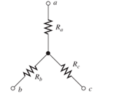
Figure P2.20
Expert Solution & Answer
Want to see the full answer?
Check out a sample textbook solution
Students have asked these similar questions
Using the circuit of below with R1 = 1 kQ, R2 = 220 Q, R3 = 10 kQ, and V = 9 volts, Determine the
theoretical voltages across R1, R2 and R3. Apply Kirchhoff's Current Law and Ohm's Law to determine
the expected currents Is. I1, l2 and I3. Record these values.
R1
1k
R3
10k
13
R2
9Vdc
220
How does the voltage across R1 compare with that through R2? What is the connection between the total current in the circuit and
the current through the two resistors? (This is known as Kirchhoff's junction rule.)
...
R1
R2
Circuit 4
If you use Circuit 5, do the same rules apply?
R1 R2SR3
Circuit 5
Q2. I- For the voltage divider circuit below,
(R1 = R2 = R3 = 10 kN, R4 = R5 =1 kn, Vi = 15V),
(ZD1 & ZD2 are Zener diodes, zener voltage = 5.6 V)
LED 1 and LED 2 are light emitting diodes
R1
R2
R3
Vi
ZD1
ZD2
LED1
LED2
R4
R5
I. What is the status of each LED (ON or OFF),
LED1 ---- ON
-----
LED 2
----- OFE
II. What is the current in R4
5 x 10⁻³
--.
III. What is the purpose of resistors R4 and R5,
------ current limiter ----
Chapter 2 Solutions
Electrical Engineering: Principles & Applications (7th Edition)
Ch. 2 - Reduce each of the networks shown in Figure P2.1...Ch. 2 - A 4- resistance is in series with the parallel...Ch. 2 - Find the equivalent resistance looking into...Ch. 2 - Suppose that we need a resistance of 1.5 k and...Ch. 2 - Find the equivalent resistance between terminals a...Ch. 2 - Find the equivalent resistance between terminals a...Ch. 2 - What resistance in parallel with 120 results in...Ch. 2 - Determine the resistance between terminals a and b...Ch. 2 - Two resistances having values of R and 2R are in...Ch. 2 - A network connected between terminals a and b...
Ch. 2 - Two resistances R1 and R2 are connected in...Ch. 2 - Find the equivalent resistance for the infinite...Ch. 2 - If we connect n 1000- resistances in parallel,...Ch. 2 - The heating element of an electric cook top has...Ch. 2 - We are designing an electric space heater to...Ch. 2 - Sometimes, we can use symmetry considerations to...Ch. 2 - The equivalent resistance between terminals a and...Ch. 2 - Three conductances G1 G2, and G3 are in series....Ch. 2 - Most sources of electrical power behave as...Ch. 2 - The resistance for the network shown in Figure...Ch. 2 - Often, we encounter delta-connected loads such as...Ch. 2 - What are the steps in solving a circuit by network...Ch. 2 - Find the values of i1 and i2 in Figure P2.23....Ch. 2 - Find the voltages v1 and v2 for the circuit shown...Ch. 2 - Find the values of v and i in Figure P2.25. Figure...Ch. 2 - Consider the circuit shown in Figure P2.24....Ch. 2 - Find the voltage v and the currents i1 and 12 for...Ch. 2 - Find the values of vs, v1, and i2 in Figure P2.28....Ch. 2 - Find the values of i1 and i2 in Figure P2.29....Ch. 2 - Consider the cirrcuit shown in Figure P2.30 Find...Ch. 2 - Solve for the values of i1, i2, and the powers for...Ch. 2 - The 12-V source in Figure P2.32 is delivering 36...Ch. 2 - Refer to the circuit shown in Figure P2.33. With...Ch. 2 - Find the values of i1 and i2 in Figure P2.34. Find...Ch. 2 - Find the values of i1 and i2 in Figure P2.35...Ch. 2 - Use the voltage-division principle to calculate...Ch. 2 - Use the current-division principle to calculate i1...Ch. 2 - Use the voltage-division principle to calculate...Ch. 2 - Use the current-division principle to calculate...Ch. 2 - Suppose we need to design a voltage-divider...Ch. 2 - A source supplies 120 V to the series combination...Ch. 2 - We have a 60- resistance, a 20- resistance, and...Ch. 2 - A worker is standing on a wet concrete floor,...Ch. 2 - Suppose we have a load that absorbs power and...Ch. 2 - We have a load resistance of 50 that we wish to...Ch. 2 - We have a load resistance of 1 k that we wish to...Ch. 2 - The circuit of Figure P2.47 is similar to networks...Ch. 2 - Write equations and solve for the node voltages...Ch. 2 - Solve for the node voltages shown in Figure P2.49....Ch. 2 - Solve for the node voltages shown in Figure P2.50....Ch. 2 - Given R1=4 , R2=5 , R2=8 , R4=10 , R5=2 , and...Ch. 2 - Determine the value of i1 in Figure P2.52 using...Ch. 2 - Given R1=15 , R5=5 , R3=20 , R4=10 , R5=8 , R6=4 ,...Ch. 2 - In solving a network, what rule must you observe...Ch. 2 - Use the symbolic features of MATLAB to find an...Ch. 2 - Solve for the values of the node voltages shown in...Ch. 2 - Solve for the node voltages shown in Figure P2.57....Ch. 2 - Solve for the power delivered to the 8- ...Ch. 2 - Solve for the node voltages shown in Figure P2.59....Ch. 2 - Find the equivalent resistance looking into...Ch. 2 - Find the equivalent resistance looking into...Ch. 2 - Figure P2.62 shows an unusual voltage-divider...Ch. 2 - Solve for the node voltages in the circuit of...Ch. 2 - We have a cube with 1- resistances along each...Ch. 2 - Solve for the power delivered to the 15- resistor...Ch. 2 - Determine the value of v2 and the power delivered...Ch. 2 - Use mesh-current analysis to find the value of i1...Ch. 2 - Solve for the power delivered by the voltage...Ch. 2 - Use mesh-current analysis to find the value of v...Ch. 2 - Use mesh-current analysis to find the value of i3...Ch. 2 - Use mesh-current analysis to find the values of i1...Ch. 2 - Find the power delivered by the source and the...Ch. 2 - Use mesh-current analysis to find the values of i1...Ch. 2 - Use mesh-current analysis to find the values of i1...Ch. 2 - The circuit shown in Figure P2.75 is the dc...Ch. 2 - Use MATLAB and mesh-current analysis to determine...Ch. 2 - Connect a 1-V voltage source across terminals a...Ch. 2 - Connect a 1-V voltage source across the terminals...Ch. 2 - Use MATLAB to solve for the mesh currents in...Ch. 2 - Find the Thévenin and Norton equivalent circuits...Ch. 2 - We can model a certain battery as a voltage source...Ch. 2 - Find the Thévenin and Norton equivalent circuits...Ch. 2 - Find the Thévenin and Norton equivalent circuits...Ch. 2 - Find the Thévenin arid Norton equivalent circuits...Ch. 2 - An automotive battery has an open-circuit voltage...Ch. 2 - A certain two-terminal circuit has an open-circuit...Ch. 2 - If we measure the voltage at the terminals of a...Ch. 2 - Find the Thévenin and Norton equivalent circuits...Ch. 2 - Find the maximum power that can be delivered to a...Ch. 2 - Find the maximum power that can be delivered to a...Ch. 2 - Figure P2.91 shows a resistive load RL connected...Ch. 2 - Starling from the Norton equivalent circuit with a...Ch. 2 - A battery can be modeled by a voltage source Vt in...Ch. 2 - Use superposition to find the current i in Figure...Ch. 2 - Solve for is in Figure P2.49 by using...Ch. 2 - Solve the circuit shown in Figure P2.48 by using...Ch. 2 - Solve for i1 in Figure P2.34 by using...Ch. 2 - Another method of solving the circuit of Figure...Ch. 2 - Use the method of Problem P2.98 for the circuit of...Ch. 2 - Solve for the actual value of i6 for the circuit...Ch. 2 - Device A shown in Figure P2.101 has v=3i2 for i 0...Ch. 2 - The Wheatstone bridge shown in Figure 2.66 is...Ch. 2 - The Wheatstone bridge shown in Figure 2.66has...Ch. 2 - In theory, any values can be used for R1 and R3 in...Ch. 2 - Derive expressions for the Thévenin voltage and...Ch. 2 - Derive Equation 2.93 for the bridge circuit of...Ch. 2 - Prob. 2.107PCh. 2 - Explain what would happen if, in wiring the bridge...Ch. 2 - Match each entry in Table T2.1(a) with the best...Ch. 2 - Consider the circuit of Figure T2.2 with vs=96V ,...Ch. 2 - Write MATLAB code to solve for the node voltages...Ch. 2 - Write a set of equations that can be used to solve...Ch. 2 - Determine the Thévenin and Norton equivalent...Ch. 2 - According to the superposition principle, what...Ch. 2 - Determine the equivalent resistance between...Ch. 2 - Transform the 2-A current source and 6- ...
Knowledge Booster


Learn more about
Need a deep-dive on the concept behind this application? Look no further. Learn more about this topic, electrical-engineering and related others by exploring similar questions and additional content below.Similar questions
- a. Thévenin's and Norton's theorem are two examples of circuit theorem. With the help of equivalent circuits, distinguish the difference between them.arrow_forwardFor the circuit shown ,IC2 = 1mA ,VCE1 = 2V , and VCE2 = 8V 1. The value of RC is equal to ohm 2. The value of R1 is equal to ohm 3. The value of R2 is equal to ohmarrow_forwardb) The circuit in Figure Q2(b) is referred. i. Show the supernode in the circuit. Explain the reason for your answer. ii. By using nodal analysis with supernode, solve for the node voltages at each assigned nodes in the circuit. 2 A 12 V Figure Q2(b)arrow_forward
- 150 100 + VA- a -4V AVA -7V 81. B b Figure 2 shows a simplified model of a gas-discharge lamp. One characteristic of these lamps is that they exhibit negative resistance; in other words, as current increases the voltage drops further, making such lamps inherently unstable. As such, a current-limiting ballast is required. For the connection shown in the figure: 1. Find the equivalent Thevenin circuit of the lamp. 2. Find the ballast resistance needed to limit the current drawn from a 24-volt source to 6 amperes.arrow_forwardRefer to the figure. Given 2RR R2 = 3R2 - RL a) Design the power supply circuit so that y = 3v,when R,-600 Q. by Assume input voltage is 180 V. Which resistor in the circuit dissipates the most power? What is the power? c) Which resistor dissipates the least power? What is the power? R2 ww R ww I RL 14. ww- 年 wwarrow_forwardQ2 (a) With the aid of a diagram, briefly describe the Kirchoff Voltage Law. (b) For a circuit in Figure Q2(b), find the value of voltage VR4. 24Ω -W- 482 12V 36Ω 3 6Ω VR4 -W- 12Ω Figure Q2(b) For a circuit indicated in Figure Q2(c), determine the value of voltage Vo, current, I, and resistors RA and RB. (c) I RA RB + 2V, - + Vo + 10 V 2 kQ 4V.arrow_forward
- An electric circuit with two DC power supplies is shown in Figure A (E1 and E2). Assume that E1 = 200 V, E2 = 120 V, and that all resistors have similar value of R = 20. Using the Superposition theory and the Current Divider Rule, simplify the circuit and determine the current (IR6) across resistor R6.arrow_forward(a) Identify the type of circuit in Figure 4. Determine its functionalities and find the appropriate mathematical equation. Sig_1 Sig_2 Sig_3+ Sig_4 Iin. Iin. Iin Iin GND www.5 R5 www R4 www R3 ww R2 ww R1 Feedback Resistor ลบ Figure 4 Iout VOUT ◆ BUarrow_forwardGood Design Calculate the unloaded voltage Va in the following circuit. Record the calculated value in the table below. Construct the circuit using MultiSim. Energize the circuit and measure V2. Record the measured value in the table below. De-energize the circuit. Assume a 30-ka load resistor is added to the circuit as shown. Calculate the loaded voltage Viz. Record the value in the table below. Construct the circuit using MultiSim. Energize the circuit and measure Via. Record the measured value in the table below. De-energize the circuit. Parameter Calculated (V) Measured (V) Vaarrow_forward
- Three resistors of 50 N, 100 N and an unknown resistance R are connected in parallel and the combination is connected to a 25 V source. If the total current delivered by the source is 1 A, determine the following: A. The value of R (Ans. R = 100 2) B. The current in each resistor (Ans. I1 = 0.5 A, I2 = I3 = 0.25 A) C. Which resistor dissipates the highest power? Show your solution. (Ans. R1)arrow_forwardProblem 1: Vs1 = 240 Volts; Vs2 = 120 Volts; R1 = R2 = 120 Ohms; R3 = R4 = 60 Ohms. S1 closed and S2 Open; Use circuit simulations with Multisim or Pspice, or any other simulation tool of your choice. Find the nodal voltages V1 and V2 and currents IR1 IR2 IR3 IR4 through R1 R2, R3, and R4, and the powers P1, P2, P3, P4 dissipated in R1 through R4; and powers Px and Py associated Vs1 and Vs2 sources [given out or absorbed, why]. S1 Vs1 + IZ IR1 R1 IP 4 V1 IR21 M R2 R3 IR3 10 4 Problem 2: Repeat Problem 1, when S1 is open and S2 Closed; Problem 3: Repeat Problem 1, when S1 and S2 both closed; V2 IR4 R4 S2 + Vs2arrow_forward4. Consider the following circuit. 3R SR 2R a) How many distinct currents flow in this circuit? The four loops shown are labeled A - D, and the junctions are labeled a - d. b) If we had to solve for these currents, how many independent equations would we need? c) Which loops and/or junctions would you choose, if you had to solve for the currents? (Many answers are possible here.) This diagram shows several different loops and junctions in the circuit. d) Set up a system of equations that would allow you to solve for the currents.arrow_forward
arrow_back_ios
SEE MORE QUESTIONS
arrow_forward_ios
Recommended textbooks for you
 Introductory Circuit Analysis (13th Edition)Electrical EngineeringISBN:9780133923605Author:Robert L. BoylestadPublisher:PEARSON
 Delmar's Standard Textbook Of ElectricityElectrical EngineeringISBN:9781337900348Author:Stephen L. HermanPublisher:Cengage Learning
 Programmable Logic ControllersElectrical EngineeringISBN:9780073373843Author:Frank D. PetruzellaPublisher:McGraw-Hill Education
 Fundamentals of Electric CircuitsElectrical EngineeringISBN:9780078028229Author:Charles K Alexander, Matthew SadikuPublisher:McGraw-Hill Education
 Electric Circuits. (11th Edition)Electrical EngineeringISBN:9780134746968Author:James W. Nilsson, Susan RiedelPublisher:PEARSON
 Engineering ElectromagneticsElectrical EngineeringISBN:9780078028151Author:Hayt, William H. (william Hart), Jr, BUCK, John A.Publisher:Mcgraw-hill Education,
Introductory Circuit Analysis (13th Edition)
Electrical Engineering
ISBN:9780133923605
Author:Robert L. Boylestad
Publisher:PEARSON
Delmar's Standard Textbook Of Electricity
Electrical Engineering
ISBN:9781337900348
Author:Stephen L. Herman
Publisher:Cengage Learning
Programmable Logic Controllers
Electrical Engineering
ISBN:9780073373843
Author:Frank D. Petruzella
Publisher:McGraw-Hill Education
Fundamentals of Electric Circuits
Electrical Engineering
ISBN:9780078028229
Author:Charles K Alexander, Matthew Sadiku
Publisher:McGraw-Hill Education
Electric Circuits. (11th Edition)
Electrical Engineering
ISBN:9780134746968
Author:James W. Nilsson, Susan Riedel
Publisher:PEARSON
Engineering Electromagnetics
Electrical Engineering
ISBN:9780078028151
Author:Hayt, William H. (william Hart), Jr, BUCK, John A.
Publisher:Mcgraw-hill Education,
Star Delta Starter Explained - Working Principle; Author: The Engineering Mindset;https://www.youtube.com/watch?v=h89TTwlNnpY;License: Standard Youtube License