
Electrical Engineering: Principles & Applications (7th Edition)
7th Edition
ISBN: 9780134484143
Author: Allan R. Hambley
Publisher: PEARSON
expand_more
expand_more
format_list_bulleted
Concept explainers
Videos
Textbook Question
Chapter 2, Problem 2.40P
Suppose we need to design a voltage-divider circuit to provide an output voltage vo=5 V from a 15-V source as shown in Figure P2.40. The current taken from the 15-V source is to be 200 mA.
- Find the values of R1 and P2
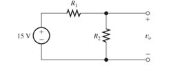
Figure P2.40
Expert Solution & Answer

Learn your wayIncludes step-by-step video

schedule03:56
Students have asked these similar questions
b) A parallel clipper circuit with a 5 V DC supply is depicted in Figure Q2b. Sketch the
output waveform V, for a complete cycle of the input Vi. Show all your analysis.
Vi
2k2 N
+10 V
+
Si
Vi
Vo
+5 V
-10 V
Figure Q2b
For the circuit shown in Figure Q2ai, drain current In is 2.26 mA and drain to source
voltage VDs is 5.22V. Calculate the values of VDD and VD?
Q2ai)
VDD
RD
2kQ
•VD
Q1
RG
ς1 2ΜΩ
RS
1kQ
Figure Q2ai
Consider a PV Module with 4 solar PV cells with the Size of each 10cm x 10cm are connected in Parallel. Choose the correct statement for the above PV Module. (Assume necessary data)
a.
The output voltage is 0.5 V, the output power is 12W
b.
The output voltage is 2 V, the output power is 12W
c.
The output voltage is 12 V, the output power is 6W
d.
The output voltage is 0.5 V, the output power is 6W
Chapter 2 Solutions
Electrical Engineering: Principles & Applications (7th Edition)
Ch. 2 - Reduce each of the networks shown in Figure P2.1...Ch. 2 - A 4- resistance is in series with the parallel...Ch. 2 - Find the equivalent resistance looking into...Ch. 2 - Suppose that we need a resistance of 1.5 k and...Ch. 2 - Find the equivalent resistance between terminals a...Ch. 2 - Find the equivalent resistance between terminals a...Ch. 2 - What resistance in parallel with 120 results in...Ch. 2 - Determine the resistance between terminals a and b...Ch. 2 - Two resistances having values of R and 2R are in...Ch. 2 - A network connected between terminals a and b...
Ch. 2 - Two resistances R1 and R2 are connected in...Ch. 2 - Find the equivalent resistance for the infinite...Ch. 2 - If we connect n 1000- resistances in parallel,...Ch. 2 - The heating element of an electric cook top has...Ch. 2 - We are designing an electric space heater to...Ch. 2 - Sometimes, we can use symmetry considerations to...Ch. 2 - The equivalent resistance between terminals a and...Ch. 2 - Three conductances G1 G2, and G3 are in series....Ch. 2 - Most sources of electrical power behave as...Ch. 2 - The resistance for the network shown in Figure...Ch. 2 - Often, we encounter delta-connected loads such as...Ch. 2 - What are the steps in solving a circuit by network...Ch. 2 - Find the values of i1 and i2 in Figure P2.23....Ch. 2 - Find the voltages v1 and v2 for the circuit shown...Ch. 2 - Find the values of v and i in Figure P2.25. Figure...Ch. 2 - Consider the circuit shown in Figure P2.24....Ch. 2 - Find the voltage v and the currents i1 and 12 for...Ch. 2 - Find the values of vs, v1, and i2 in Figure P2.28....Ch. 2 - Find the values of i1 and i2 in Figure P2.29....Ch. 2 - Consider the cirrcuit shown in Figure P2.30 Find...Ch. 2 - Solve for the values of i1, i2, and the powers for...Ch. 2 - The 12-V source in Figure P2.32 is delivering 36...Ch. 2 - Refer to the circuit shown in Figure P2.33. With...Ch. 2 - Find the values of i1 and i2 in Figure P2.34. Find...Ch. 2 - Find the values of i1 and i2 in Figure P2.35...Ch. 2 - Use the voltage-division principle to calculate...Ch. 2 - Use the current-division principle to calculate i1...Ch. 2 - Use the voltage-division principle to calculate...Ch. 2 - Use the current-division principle to calculate...Ch. 2 - Suppose we need to design a voltage-divider...Ch. 2 - A source supplies 120 V to the series combination...Ch. 2 - We have a 60- resistance, a 20- resistance, and...Ch. 2 - A worker is standing on a wet concrete floor,...Ch. 2 - Suppose we have a load that absorbs power and...Ch. 2 - We have a load resistance of 50 that we wish to...Ch. 2 - We have a load resistance of 1 k that we wish to...Ch. 2 - The circuit of Figure P2.47 is similar to networks...Ch. 2 - Write equations and solve for the node voltages...Ch. 2 - Solve for the node voltages shown in Figure P2.49....Ch. 2 - Solve for the node voltages shown in Figure P2.50....Ch. 2 - Given R1=4 , R2=5 , R2=8 , R4=10 , R5=2 , and...Ch. 2 - Determine the value of i1 in Figure P2.52 using...Ch. 2 - Given R1=15 , R5=5 , R3=20 , R4=10 , R5=8 , R6=4 ,...Ch. 2 - In solving a network, what rule must you observe...Ch. 2 - Use the symbolic features of MATLAB to find an...Ch. 2 - Solve for the values of the node voltages shown in...Ch. 2 - Solve for the node voltages shown in Figure P2.57....Ch. 2 - Solve for the power delivered to the 8- ...Ch. 2 - Solve for the node voltages shown in Figure P2.59....Ch. 2 - Find the equivalent resistance looking into...Ch. 2 - Find the equivalent resistance looking into...Ch. 2 - Figure P2.62 shows an unusual voltage-divider...Ch. 2 - Solve for the node voltages in the circuit of...Ch. 2 - We have a cube with 1- resistances along each...Ch. 2 - Solve for the power delivered to the 15- resistor...Ch. 2 - Determine the value of v2 and the power delivered...Ch. 2 - Use mesh-current analysis to find the value of i1...Ch. 2 - Solve for the power delivered by the voltage...Ch. 2 - Use mesh-current analysis to find the value of v...Ch. 2 - Use mesh-current analysis to find the value of i3...Ch. 2 - Use mesh-current analysis to find the values of i1...Ch. 2 - Find the power delivered by the source and the...Ch. 2 - Use mesh-current analysis to find the values of i1...Ch. 2 - Use mesh-current analysis to find the values of i1...Ch. 2 - The circuit shown in Figure P2.75 is the dc...Ch. 2 - Use MATLAB and mesh-current analysis to determine...Ch. 2 - Connect a 1-V voltage source across terminals a...Ch. 2 - Connect a 1-V voltage source across the terminals...Ch. 2 - Use MATLAB to solve for the mesh currents in...Ch. 2 - Find the Thévenin and Norton equivalent circuits...Ch. 2 - We can model a certain battery as a voltage source...Ch. 2 - Find the Thévenin and Norton equivalent circuits...Ch. 2 - Find the Thévenin and Norton equivalent circuits...Ch. 2 - Find the Thévenin arid Norton equivalent circuits...Ch. 2 - An automotive battery has an open-circuit voltage...Ch. 2 - A certain two-terminal circuit has an open-circuit...Ch. 2 - If we measure the voltage at the terminals of a...Ch. 2 - Find the Thévenin and Norton equivalent circuits...Ch. 2 - Find the maximum power that can be delivered to a...Ch. 2 - Find the maximum power that can be delivered to a...Ch. 2 - Figure P2.91 shows a resistive load RL connected...Ch. 2 - Starling from the Norton equivalent circuit with a...Ch. 2 - A battery can be modeled by a voltage source Vt in...Ch. 2 - Use superposition to find the current i in Figure...Ch. 2 - Solve for is in Figure P2.49 by using...Ch. 2 - Solve the circuit shown in Figure P2.48 by using...Ch. 2 - Solve for i1 in Figure P2.34 by using...Ch. 2 - Another method of solving the circuit of Figure...Ch. 2 - Use the method of Problem P2.98 for the circuit of...Ch. 2 - Solve for the actual value of i6 for the circuit...Ch. 2 - Device A shown in Figure P2.101 has v=3i2 for i 0...Ch. 2 - The Wheatstone bridge shown in Figure 2.66 is...Ch. 2 - The Wheatstone bridge shown in Figure 2.66has...Ch. 2 - In theory, any values can be used for R1 and R3 in...Ch. 2 - Derive expressions for the Thévenin voltage and...Ch. 2 - Derive Equation 2.93 for the bridge circuit of...Ch. 2 - Prob. 2.107PCh. 2 - Explain what would happen if, in wiring the bridge...Ch. 2 - Match each entry in Table T2.1(a) with the best...Ch. 2 - Consider the circuit of Figure T2.2 with vs=96V ,...Ch. 2 - Write MATLAB code to solve for the node voltages...Ch. 2 - Write a set of equations that can be used to solve...Ch. 2 - Determine the Thévenin and Norton equivalent...Ch. 2 - According to the superposition principle, what...Ch. 2 - Determine the equivalent resistance between...Ch. 2 - Transform the 2-A current source and 6- ...
Additional Engineering Textbook Solutions
Find more solutions based on key concepts
An electron with a speed of 8 106 m/s is projected along the positive x direction into a medium containing a u...
Fundamentals of Applied Electromagnetics (7th Edition)
The switch in the circuit shown has been closed for a long time and is opened at t = 0.
Calculate the initial v...
Electric Circuits (10th Edition)
A wire 1000 ft long has a resistance of 0.5 and an area of 94 CM. Of what material is the wire made (T=20C)?
Introductory Circuit Analysis (13th Edition)
In the circuit shown in Fig. P 7.26, both switches operate together; that is, they either open or close at the ...
Electric Circuits. (11th Edition)
Why might doctors and nutritionists be interested in a device like DietSensor?
Using MIS (10th Edition)
Write a nested loop that displays 10 rows of # characters. There should be 15 # characters in each row.
Starting Out with Java: From Control Structures through Objects (7th Edition) (What's New in Computer Science)
Knowledge Booster


Learn more about
Need a deep-dive on the concept behind this application? Look no further. Learn more about this topic, electrical-engineering and related others by exploring similar questions and additional content below.Similar questions
- QUESTION 2 a) b) Figure Q2a shows a parallel clipper circuit. Analyze the circuit and hence sketch the output waveform for one complete cycle of the input. R own V₁ 10 Vi (V) A -20 15- -15 t(s) t(s) Figure Q2a Determine the output voltage, V, and hence sketch the output voltage waveform for the clamper circuit shown in Figure Q2b. C Figure Q2b Si Si 5 V 3V V₂ R Voarrow_forwardis made from a combination of A mixed resistors circuit as shown in Figure parallel and series circuits. The values of the resistances mentioned in the circuit are in Ohm (2) and the supply voltage is in Volt (V). Determine the: (i) Current through the circuit (I). (ii) Voltage drop (V) across the circuit. 0.6 0 4 0 0.5 0arrow_forwardQ2. I- For the voltage divider circuit below, (R1 = R2 = R3 = 10 kN, R4 = R5 =1 kn, Vi = 15V), (ZD1 & ZD2 are Zener diodes, zener voltage = 5.6 V) LED 1 and LED 2 are light emitting diodes R1 R2 R3 Vi ZD1 ZD2 LED1 LED2 R4 R5 I. What is the status of each LED (ON or OFF), LED1 ---- ON ----- LED 2 ----- OFE II. What is the current in R4 5 x 10⁻³ --. III. What is the purpose of resistors R4 and R5, ------ current limiter ----arrow_forward
- answer as soon C) Figure Q2(c) shows a simple electronic circuit. A recently graduated engineering student from eau has been tasked by his Senior Engineer to determine the equivalent circuit between Terminal A and B. Please help him to analyze and find the equivalent resistance using delta-wye transformationarrow_forward1. A VBE multiplier (see Figure 1) is designed with equal resistances for operation at bias current of 1 mA with half current flowing in the bias network. The initial design is based on B=0 and VBE=0.7V at 1 mA. Find the required resistor values and the biasing voltage VBB. You can assume that VBE is 0.7V for all currents (constant voltage drop model) +Vcc IBIAS R2 VBB RL -Vcc Figure 1. A class AB output stage utilizing a VBEmultiplier for biasingarrow_forwardWhat is the zener current for the circuit shown? Please choose one: a. 6.0 mA b. 9.0 mA c. 7.5 mA D. 3.0 mAarrow_forward
- Sy A circuit design calls a 1.5 kN resistor to have 4.7 V across its terminals. What would be the expected current? The circuit is built, and the resistance is measured at 1500 2 and the voltage at 4.7 V. What is the current through the resistor? f is iearrow_forwardQ2. A 7.2 V zener is used in the circuit shown in Figure below and the load current is to vary from 12 to 100 mA. Find the value of series resistance R to maintain a voltage of 7.2 V across the load. The input voltage is constant at 12V and the minimum zener current is 10 mA. win IL R Iz E = 12 V RLarrow_forwardTwo batteries are connected in parallel delivering power to a power resistor. The first battery has an open circuit voltage of 12.6 V and an internal resistance of 0.2 ohm. The second battery has an open circuit voltage of 12.2 V and an internal resistance of 0.3 ohm. Find the maximum power delivered to the load resistance.arrow_forward
- 1. A voltage divider provides 1 V output from 5 V input. The maximum output current is 1 mA. The resistors are chosen to provide load regulation of better than 1% over the load current range of 0-1 mA. Find the resistor values necessary for this application. What is the efficiency at full load?arrow_forwardWhat is the load current for the circuit shown in the figure? Please choose one: a. 9.0 mA b. 7.5 mA c. 3.0 mA D. 6.0 mAarrow_forwardThree resistors of 50 N, 100 N and an unknown resistance R are connected in parallel and the combination is connected to a 25 V source. If the total current delivered by the source is 1 A, determine the following: A. The value of R (Ans. R = 100 2) B. The current in each resistor (Ans. I1 = 0.5 A, I2 = I3 = 0.25 A) C. Which resistor dissipates the highest power? Show your solution. (Ans. R1)arrow_forward
arrow_back_ios
SEE MORE QUESTIONS
arrow_forward_ios
Recommended textbooks for you
 Introductory Circuit Analysis (13th Edition)Electrical EngineeringISBN:9780133923605Author:Robert L. BoylestadPublisher:PEARSON
 Delmar's Standard Textbook Of ElectricityElectrical EngineeringISBN:9781337900348Author:Stephen L. HermanPublisher:Cengage Learning
 Programmable Logic ControllersElectrical EngineeringISBN:9780073373843Author:Frank D. PetruzellaPublisher:McGraw-Hill Education
 Fundamentals of Electric CircuitsElectrical EngineeringISBN:9780078028229Author:Charles K Alexander, Matthew SadikuPublisher:McGraw-Hill Education
 Electric Circuits. (11th Edition)Electrical EngineeringISBN:9780134746968Author:James W. Nilsson, Susan RiedelPublisher:PEARSON
 Engineering ElectromagneticsElectrical EngineeringISBN:9780078028151Author:Hayt, William H. (william Hart), Jr, BUCK, John A.Publisher:Mcgraw-hill Education,
Introductory Circuit Analysis (13th Edition)
Electrical Engineering
ISBN:9780133923605
Author:Robert L. Boylestad
Publisher:PEARSON
Delmar's Standard Textbook Of Electricity
Electrical Engineering
ISBN:9781337900348
Author:Stephen L. Herman
Publisher:Cengage Learning
Programmable Logic Controllers
Electrical Engineering
ISBN:9780073373843
Author:Frank D. Petruzella
Publisher:McGraw-Hill Education
Fundamentals of Electric Circuits
Electrical Engineering
ISBN:9780078028229
Author:Charles K Alexander, Matthew Sadiku
Publisher:McGraw-Hill Education
Electric Circuits. (11th Edition)
Electrical Engineering
ISBN:9780134746968
Author:James W. Nilsson, Susan Riedel
Publisher:PEARSON
Engineering Electromagnetics
Electrical Engineering
ISBN:9780078028151
Author:Hayt, William H. (william Hart), Jr, BUCK, John A.
Publisher:Mcgraw-hill Education,
Star Delta Starter Explained - Working Principle; Author: The Engineering Mindset;https://www.youtube.com/watch?v=h89TTwlNnpY;License: Standard Youtube License