
Electrical Engineering: Principles & Applications (7th Edition)
7th Edition
ISBN: 9780134484143
Author: Allan R. Hambley
Publisher: PEARSON
expand_more
expand_more
format_list_bulleted
Concept explainers
Videos
Textbook Question
Chapter 2, Problem 2.2PT
Consider the circuit of Figure T2.2 with
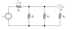
Figure T2.2
Expert Solution & Answer
Want to see the full answer?
Check out a sample textbook solution
Students have asked these similar questions
Determine the mathematical model equations for the electrical circuit shown in
figure 2. The circuit is consisting of two resistors, two inductors and a capacitor. A
voltage Va is applied to the circuit. Derive an expression for the mathematical model
of the following circuit.
R1
L2
i1
13
14
16
+ O-
i2
i5
R2
L1
Va
C
Figure (2) the electrical circuit
u
a) Based on Figure Q1(a), prove that the voltage across resistor R₂ is;
R3
R₁ + R₂ + R3
VT
VR3
=
VRI
+
VR2
VR3
Figure Q1(a)
-VT
R₁
R₂
R3
Consider the circuit shown in the figure below. (Let R₁ = 6.00 0, R₂ = 8.00 0, and 8 - 10.0 V.)
2.000
W
10.00
www
5.000
www
&
16
(a) Find the voltage across R₁.
(b) Find the current in R₁.
R₂
www
Chapter 2 Solutions
Electrical Engineering: Principles & Applications (7th Edition)
Ch. 2 - Reduce each of the networks shown in Figure P2.1...Ch. 2 - A 4- resistance is in series with the parallel...Ch. 2 - Find the equivalent resistance looking into...Ch. 2 - Suppose that we need a resistance of 1.5 k and...Ch. 2 - Find the equivalent resistance between terminals a...Ch. 2 - Find the equivalent resistance between terminals a...Ch. 2 - What resistance in parallel with 120 results in...Ch. 2 - Determine the resistance between terminals a and b...Ch. 2 - Two resistances having values of R and 2R are in...Ch. 2 - A network connected between terminals a and b...
Ch. 2 - Two resistances R1 and R2 are connected in...Ch. 2 - Find the equivalent resistance for the infinite...Ch. 2 - If we connect n 1000- resistances in parallel,...Ch. 2 - The heating element of an electric cook top has...Ch. 2 - We are designing an electric space heater to...Ch. 2 - Sometimes, we can use symmetry considerations to...Ch. 2 - The equivalent resistance between terminals a and...Ch. 2 - Three conductances G1 G2, and G3 are in series....Ch. 2 - Most sources of electrical power behave as...Ch. 2 - The resistance for the network shown in Figure...Ch. 2 - Often, we encounter delta-connected loads such as...Ch. 2 - What are the steps in solving a circuit by network...Ch. 2 - Find the values of i1 and i2 in Figure P2.23....Ch. 2 - Find the voltages v1 and v2 for the circuit shown...Ch. 2 - Find the values of v and i in Figure P2.25. Figure...Ch. 2 - Consider the circuit shown in Figure P2.24....Ch. 2 - Find the voltage v and the currents i1 and 12 for...Ch. 2 - Find the values of vs, v1, and i2 in Figure P2.28....Ch. 2 - Find the values of i1 and i2 in Figure P2.29....Ch. 2 - Consider the cirrcuit shown in Figure P2.30 Find...Ch. 2 - Solve for the values of i1, i2, and the powers for...Ch. 2 - The 12-V source in Figure P2.32 is delivering 36...Ch. 2 - Refer to the circuit shown in Figure P2.33. With...Ch. 2 - Find the values of i1 and i2 in Figure P2.34. Find...Ch. 2 - Find the values of i1 and i2 in Figure P2.35...Ch. 2 - Use the voltage-division principle to calculate...Ch. 2 - Use the current-division principle to calculate i1...Ch. 2 - Use the voltage-division principle to calculate...Ch. 2 - Use the current-division principle to calculate...Ch. 2 - Suppose we need to design a voltage-divider...Ch. 2 - A source supplies 120 V to the series combination...Ch. 2 - We have a 60- resistance, a 20- resistance, and...Ch. 2 - A worker is standing on a wet concrete floor,...Ch. 2 - Suppose we have a load that absorbs power and...Ch. 2 - We have a load resistance of 50 that we wish to...Ch. 2 - We have a load resistance of 1 k that we wish to...Ch. 2 - The circuit of Figure P2.47 is similar to networks...Ch. 2 - Write equations and solve for the node voltages...Ch. 2 - Solve for the node voltages shown in Figure P2.49....Ch. 2 - Solve for the node voltages shown in Figure P2.50....Ch. 2 - Given R1=4 , R2=5 , R2=8 , R4=10 , R5=2 , and...Ch. 2 - Determine the value of i1 in Figure P2.52 using...Ch. 2 - Given R1=15 , R5=5 , R3=20 , R4=10 , R5=8 , R6=4 ,...Ch. 2 - In solving a network, what rule must you observe...Ch. 2 - Use the symbolic features of MATLAB to find an...Ch. 2 - Solve for the values of the node voltages shown in...Ch. 2 - Solve for the node voltages shown in Figure P2.57....Ch. 2 - Solve for the power delivered to the 8- ...Ch. 2 - Solve for the node voltages shown in Figure P2.59....Ch. 2 - Find the equivalent resistance looking into...Ch. 2 - Find the equivalent resistance looking into...Ch. 2 - Figure P2.62 shows an unusual voltage-divider...Ch. 2 - Solve for the node voltages in the circuit of...Ch. 2 - We have a cube with 1- resistances along each...Ch. 2 - Solve for the power delivered to the 15- resistor...Ch. 2 - Determine the value of v2 and the power delivered...Ch. 2 - Use mesh-current analysis to find the value of i1...Ch. 2 - Solve for the power delivered by the voltage...Ch. 2 - Use mesh-current analysis to find the value of v...Ch. 2 - Use mesh-current analysis to find the value of i3...Ch. 2 - Use mesh-current analysis to find the values of i1...Ch. 2 - Find the power delivered by the source and the...Ch. 2 - Use mesh-current analysis to find the values of i1...Ch. 2 - Use mesh-current analysis to find the values of i1...Ch. 2 - The circuit shown in Figure P2.75 is the dc...Ch. 2 - Use MATLAB and mesh-current analysis to determine...Ch. 2 - Connect a 1-V voltage source across terminals a...Ch. 2 - Connect a 1-V voltage source across the terminals...Ch. 2 - Use MATLAB to solve for the mesh currents in...Ch. 2 - Find the Thévenin and Norton equivalent circuits...Ch. 2 - We can model a certain battery as a voltage source...Ch. 2 - Find the Thévenin and Norton equivalent circuits...Ch. 2 - Find the Thévenin and Norton equivalent circuits...Ch. 2 - Find the Thévenin arid Norton equivalent circuits...Ch. 2 - An automotive battery has an open-circuit voltage...Ch. 2 - A certain two-terminal circuit has an open-circuit...Ch. 2 - If we measure the voltage at the terminals of a...Ch. 2 - Find the Thévenin and Norton equivalent circuits...Ch. 2 - Find the maximum power that can be delivered to a...Ch. 2 - Find the maximum power that can be delivered to a...Ch. 2 - Figure P2.91 shows a resistive load RL connected...Ch. 2 - Starling from the Norton equivalent circuit with a...Ch. 2 - A battery can be modeled by a voltage source Vt in...Ch. 2 - Use superposition to find the current i in Figure...Ch. 2 - Solve for is in Figure P2.49 by using...Ch. 2 - Solve the circuit shown in Figure P2.48 by using...Ch. 2 - Solve for i1 in Figure P2.34 by using...Ch. 2 - Another method of solving the circuit of Figure...Ch. 2 - Use the method of Problem P2.98 for the circuit of...Ch. 2 - Solve for the actual value of i6 for the circuit...Ch. 2 - Device A shown in Figure P2.101 has v=3i2 for i 0...Ch. 2 - The Wheatstone bridge shown in Figure 2.66 is...Ch. 2 - The Wheatstone bridge shown in Figure 2.66has...Ch. 2 - In theory, any values can be used for R1 and R3 in...Ch. 2 - Derive expressions for the Thévenin voltage and...Ch. 2 - Derive Equation 2.93 for the bridge circuit of...Ch. 2 - Prob. 2.107PCh. 2 - Explain what would happen if, in wiring the bridge...Ch. 2 - Match each entry in Table T2.1(a) with the best...Ch. 2 - Consider the circuit of Figure T2.2 with vs=96V ,...Ch. 2 - Write MATLAB code to solve for the node voltages...Ch. 2 - Write a set of equations that can be used to solve...Ch. 2 - Determine the Thévenin and Norton equivalent...Ch. 2 - According to the superposition principle, what...Ch. 2 - Determine the equivalent resistance between...Ch. 2 - Transform the 2-A current source and 6- ...
Knowledge Booster


Learn more about
Need a deep-dive on the concept behind this application? Look no further. Learn more about this topic, electrical-engineering and related others by exploring similar questions and additional content below.Similar questions
- Connect the circuit shown in figure below and let Vs = 8V. R1 = 50 Q, R2= 220 Q, R3 = 330 Q. Calculate I, I, and Iz. 12(A R1=50 2 Vs=8 V R2=220 2 R3=330 2arrow_forwardDesign a circuit that will have an outcome of the highest equivalent resistance across the terminals with a 30Vdc source. Given that the R1 = 10 R2 = 50 R3 = 85. Determine the equivalent resistance from the combination of resistors, R123, R12, R23, and R1.arrow_forwardConsider the circuit diagram below. Given I = 2.5 mA and Is = 1.25 mA: a) Find the currents Is2, I2, I3, I4 and Iz. State your conclusion as a table of values. b) What is the voltage drop across R7? c) If Vab = 2.75 V, what is the value of Rs?arrow_forward
- *P2.67. Solve for the power delivered to the 24-S2 resistor and for the mesh currents shown in Figure P2.67. 8Ω 16 2 25 V 24 N i2 15 V Figure P2.67arrow_forwardRefer to the following circuit diagram. Find the current Is1 supplied by source E₁. and current Is2 supplied by E2. E₁ 130V Ist A Z₁ 3352 N Z₂ 1052 B D Z₁ 2402 Z 502 C Isz E₂ 110Varrow_forwardConsider the circuit shown in below Figure, Find values of the resistances R1 and R2 that cause the voltages v1 and v2 to be v1 = 1 V and v2 = 2 V. 500 2 + + R1 R2 () 5 mA 3 mA V1 V2 6:03 PM 50°F Clear 2/18/2022 P Type here to search Del End F10 PgUp. F11 PgDn F12 PrtScn Home F7 F2 F3 F1 & ) Backspace %23 %24 % 4. 5 7 8. 9. 2 3 W.arrow_forward
- Given that: R1=31, R2=25, Is=7.4 A, Vs=7.1 V, Find Vth between the terminals a-b for the circuit shown below R2 Q 6Ω b a R2Q ZR1Q (4 is A VsV Select one: O a. 229.4 Ob. 3.550000 O. 232.950000 O d. none of the above O e. -225.850000arrow_forwardQ2 Find the system response vo(t) for the circuit illustrated by Figure Q2. 2Ω. V.(t) e -5t u(t) 0.25 F Figure Q2arrow_forward14. The circuit fragment shown in Figure is called a voltage divider. (a) If VR₂ (R₁+R₂)* R₁0ad is not attached, show that Vout (b) If R₁ R₂ = 10km, what is the smallest value of Rload that can be used so that Vout drops by less than 10 percent from its unloaded value? (Vout is measured with respect to ground.) Hu ww ww R₂ V out Road =arrow_forward
- b) The circuit in Figure Q2(b) is referred. i. Show the supernode in the circuit. Explain the reason for your answer. ii. By using nodal analysis with supernode, solve for the node voltages at each assigned nodes in the circuit. 2 A 12 V Figure Q2(b)arrow_forwardSince R1=3538.58ohm, R2=5870.13ohm and Ri-Infinite in the circuit given in the figure, write the equivalent resistance seen between AB terminals in Ohms. R1 Kuvvetlendirici R2 Ri B A.arrow_forwardThe bridge circuit shown is balanced when R1, =100 ?, R2 = 1000 ? and R3 150 ? The bridge is energized from a 5 V dc source. a) What is the value of R,? b) Suppose each bridge resistor is capable of dissipating 250 mw. Can the bridge be left in the balanced state without exceeding the power-dissipating capacity of the resistors, thereby damaging the bridge? R1 R2 Rx R3arrow_forward
arrow_back_ios
SEE MORE QUESTIONS
arrow_forward_ios
Recommended textbooks for you
 Introductory Circuit Analysis (13th Edition)Electrical EngineeringISBN:9780133923605Author:Robert L. BoylestadPublisher:PEARSON
 Delmar's Standard Textbook Of ElectricityElectrical EngineeringISBN:9781337900348Author:Stephen L. HermanPublisher:Cengage Learning
 Programmable Logic ControllersElectrical EngineeringISBN:9780073373843Author:Frank D. PetruzellaPublisher:McGraw-Hill Education
 Fundamentals of Electric CircuitsElectrical EngineeringISBN:9780078028229Author:Charles K Alexander, Matthew SadikuPublisher:McGraw-Hill Education
 Electric Circuits. (11th Edition)Electrical EngineeringISBN:9780134746968Author:James W. Nilsson, Susan RiedelPublisher:PEARSON
 Engineering ElectromagneticsElectrical EngineeringISBN:9780078028151Author:Hayt, William H. (william Hart), Jr, BUCK, John A.Publisher:Mcgraw-hill Education,
Introductory Circuit Analysis (13th Edition)
Electrical Engineering
ISBN:9780133923605
Author:Robert L. Boylestad
Publisher:PEARSON
Delmar's Standard Textbook Of Electricity
Electrical Engineering
ISBN:9781337900348
Author:Stephen L. Herman
Publisher:Cengage Learning
Programmable Logic Controllers
Electrical Engineering
ISBN:9780073373843
Author:Frank D. Petruzella
Publisher:McGraw-Hill Education
Fundamentals of Electric Circuits
Electrical Engineering
ISBN:9780078028229
Author:Charles K Alexander, Matthew Sadiku
Publisher:McGraw-Hill Education
Electric Circuits. (11th Edition)
Electrical Engineering
ISBN:9780134746968
Author:James W. Nilsson, Susan Riedel
Publisher:PEARSON
Engineering Electromagnetics
Electrical Engineering
ISBN:9780078028151
Author:Hayt, William H. (william Hart), Jr, BUCK, John A.
Publisher:Mcgraw-hill Education,
Current Divider Rule; Author: Neso Academy;https://www.youtube.com/watch?v=hRU1mKWUehY;License: Standard YouTube License, CC-BY