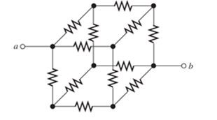
Sometimes, we can use symmetry considerations to find the resistance of a circuit that cannot be reduced by series or parallel combinations. A classic problem of this type is illustrated in Figure P2.16. Twelve 1- Ω resistors are arranged on the edges of a cube, and terminals a and b are connected to diagonally opposite corners of the cube. The problem is to find the resistance between the terminals. Approach the problem this way: Assume that 1 A of current enters terminal a and exits through terminal b. Then, the voltage between terminals a and b is equal to the unknown resistance. By symmetry considerations, we can find the current in each resistor. Then, using KVL, we can find the voltage between a and b. Figure P2.16 Each resistor has a value of 1 Ω .
Sometimes, we can use symmetry considerations to find the resistance of a circuit that cannot be reduced by series or parallel combinations. A classic problem of this type is illustrated in Figure P2.16. Twelve 1- Ω resistors are arranged on the edges of a cube, and terminals a and b are connected to diagonally opposite corners of the cube. The problem is to find the resistance between the terminals. Approach the problem this way: Assume that 1 A of current enters terminal a and exits through terminal b. Then, the voltage between terminals a and b is equal to the unknown resistance. By symmetry considerations, we can find the current in each resistor. Then, using KVL, we can find the voltage between a and b. Figure P2.16 Each resistor has a value of 1 Ω .
Solution Summary: The circuit is shown in Figure 1. Mark the nodes and the current directions and redraw the circuit.
Sometimes, we can use symmetry considerations to find the resistance of a circuit that cannot be reduced by series or parallel combinations. A classic problem of this type is illustrated in Figure P2.16. Twelve 1-
Ω
resistors are arranged on the edges of a cube, and terminals a and b are connected to diagonally opposite corners of the cube. The problem is to find the resistance between the terminals. Approach the problem this way: Assume that 1 A of current enters terminal a and exits through terminal b. Then, the voltage between terminals a and b is equal to the unknown resistance. By symmetry considerations, we can find the current in each resistor. Then, using KVL, we can find the voltage between a and b.
Shown in the figure below is an electrical circuit containing three resistors and two batteries.
I₁
0=
4
+
L
.
ww
R3
R₂
ww
1₂
R₁
ww
Write down the Kirchhoff Junction equation and solve it for I, in terms of I₂ and I3. Write the result here:
1₁ = 12-13
R₂=552
R₂ = 132
13
Write down the Kirchhoff Loop equation for a loop that starts at the lower left corner and follows the perimeter of the circuit diagram clockwise.
- IzR3 − LR₁ + 14
+ 10
Write down the Kirchhoff Loop equation for a loop that starts at the lower left corner and touches the components 4V, R₂, and R₁.
0 = 4-1₂R₂-11R₁
The resistors in the circuit have the following values:
R₁ = 12
Solve for all the following (some answers may be negative):
I₁ = 27.78
X Amperes
1₂ = 28.84
X Amperes
13 = 1.060
X Amperes
NOTE: For the equations, put in resistances and currents SYMBOLICALLY using variables like R₁,R₂,R3 and 11,12,13. Use numerical values of 10 and 4 for the voltages.
A component requires 6.3-V across it with a current of 0.3 V. A second component requires 12.6-V at 0.15A. The two components are connected in series. What is the value of resistor that must be connected across the 12.6-V component to allow it to operate properly when in series with the 6.3-V component?
CAN YOU SOLVE THIS QUICKLTY
In the circuit shown in the figure, OPAMP is fed from a 15 V source. VS voltage applied to the input of the circuitPlot the VO change depending on the change.
Need a deep-dive on the concept behind this application? Look no further. Learn more about this topic, electrical-engineering and related others by exploring similar questions and additional content below.


 Introductory Circuit Analysis (13th Edition)Electrical EngineeringISBN:9780133923605Author:Robert L. BoylestadPublisher:PEARSON
 Delmar's Standard Textbook Of ElectricityElectrical EngineeringISBN:9781337900348Author:Stephen L. HermanPublisher:Cengage Learning
 Programmable Logic ControllersElectrical EngineeringISBN:9780073373843Author:Frank D. PetruzellaPublisher:McGraw-Hill Education
 Fundamentals of Electric CircuitsElectrical EngineeringISBN:9780078028229Author:Charles K Alexander, Matthew SadikuPublisher:McGraw-Hill Education
 Electric Circuits. (11th Edition)Electrical EngineeringISBN:9780134746968Author:James W. Nilsson, Susan RiedelPublisher:PEARSON
 Engineering ElectromagneticsElectrical EngineeringISBN:9780078028151Author:Hayt, William H. (william Hart), Jr, BUCK, John A.Publisher:Mcgraw-hill Education,