
Videos
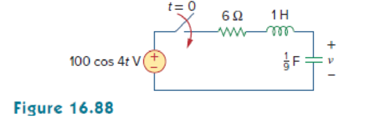
For the RLC circuit shown in Fig. 16.88, find the complete response if v(0) = 100 V when the switch is closed.
Find the expression of voltage response
Answer to Problem 65P
The expression of voltage response
Explanation of Solution
Given data:
Refer to Figure 16.88 in the textbook.
The value of initial voltage across the capacitor
Formula used:
Write a general expression to calculate the impedance of a resistor in s-domain.
Here,
Write a general expression to calculate the impedance of an inductor in s-domain.
Here,
Write a general expression to calculate the impedance of a capacitor in s-domain.
Here,
Calculation:
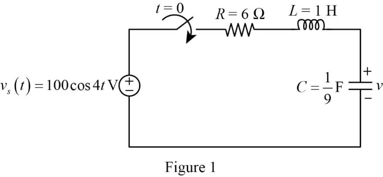
The given circuit is redrawn as shown in Figure 1.
For time
Apply Laplace transform for
Substitute
Substitute
Substitute
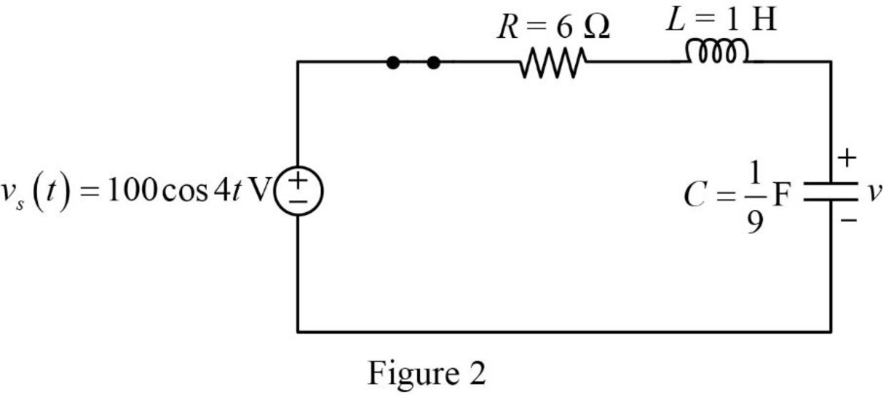
Using element transformation methods with initial conditions convert the Figure 2 into s-domain.
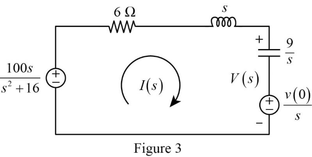
Apply Kirchhoff’s voltage law for the circuit shown in Figure 3.
Substitute
Simplify the above equation to find
Refer to Figure 3, the voltage
Substitute
Assume,
Substitute equation (5) in equation (4).
Take partial fraction for equation (5).
The equation (7) can also be written as follows:
Simplify the above equation as follows:
Simplify the above equation as follows:
Equate the co-efficient of constant term in equation (8) to find
Simplify the above equation to find
Equate the co-efficient of
Simplify the above equation to find
Substitute
Equate the co-efficient of
Substitute
Equate the co-efficient of
Substitute
Simplify the above equation to find
Equate the co-efficient of
Substitute
Substitute the equation (11) in equation (10).
Simplify the above equation as follows:
Simplify the above equation to find
Substitute equation (11) in equation (12).
Simplify the above equation as follows:
Substitute the equation (13) in above equation to find
Simplify the above equation to find
Substitute
Substitute
Substitute
Substitute
Substitute
Simplify the above equation as follows:
Take inverse Laplace transform for above equation to find
Conclusion:
Thus, the expression of voltage response
Want to see more full solutions like this?
Chapter 16 Solutions
Fundamentals of Electric Circuits


- Select such state variables for the series RLC circuit shown in the picture so that the state equations of the system can be written in the form x=Ax+Bu and y=Cx+Du. Show itarrow_forwardWhich of the following is the H (s) transfer function of the system whose block diagram is given? s / (4s + 3)4 s / (3s + 1)4 s / (3s + 2)s / (s + 4)4 s / (s + 1)3 s / (s + 4)arrow_forwardFor the above RLC circuit, select the state variables such that the stateequations of the system x = Ax+Bu y= Cx +Du can be written in form. Show it.arrow_forward
- The circuit is driven by a voltage source whosevoltage increases linearly with time, namely, vg=50tu(t) V. Use the transfer function to find vo.arrow_forwardSelect such state variables for the above RLC circuit so that the state equations of the system can be written in the form x = Ax +Bu , y=Cx+Du. Show it.arrow_forwardObtain the transfer functions X1(s)/U(s) and X2 (s)/U(s) of the mechanical system.arrow_forward
- Signal and system The mathematical model of a system is y" (t) + ay'(t) + by(t) = x" (t) + cx(t) where a=-3, b=-3 and c=-3. 1) Find zeros and poles of the system. 2) Show them onto the S-Plane (the complex plane) 3) Discuss the BIBO stability of the system.arrow_forwardA system is described by the differential equation (see attached). a)What is the order of the system. How many poles does the system's transfer function have. How many states are needed to describe the system completely.b) Determine the system's transfer function, Y(s)/U(s) (the poles of the system are at ―1, ― 2, and ―4);c) Determine matrices A, B, C, and D to describe the system in state-space form x' = Ax + Bu, y = Cx + Du.arrow_forwardThe block diagram of a time-invariant, linear, continuous-time system is given below. X1(s) and X2(s) are the state variables of the system. U(s) is the input signal of the system, Y(s) is the output signal of the system. What is the value of parameter E?arrow_forward
- Convert differential equations to transfer functionarrow_forwardThe mathematical model of a system is 1y" (t) + 2y' (t) + 1y (t) = 1x' (t) + 2x (t) and the initial conditions are y(0) = 1 and y' (0) = 2. 1) Find the transfer function. 2) Find the system output when the input is Xt) = U(t).arrow_forwardby applying kirchhoff's voltage law to a series RLC circuit, we obtain the relationship; 2*d^2i/dt^2+6*di/dt+4*i=10*e^-3t, use laplace transforms to find equation for i, given the initial conditions t = 0, i = 0, di/dt = 5arrow_forward
 Introductory Circuit Analysis (13th Edition)Electrical EngineeringISBN:9780133923605Author:Robert L. BoylestadPublisher:PEARSON
 Delmar's Standard Textbook Of ElectricityElectrical EngineeringISBN:9781337900348Author:Stephen L. HermanPublisher:Cengage Learning
 Programmable Logic ControllersElectrical EngineeringISBN:9780073373843Author:Frank D. PetruzellaPublisher:McGraw-Hill Education
 Fundamentals of Electric CircuitsElectrical EngineeringISBN:9780078028229Author:Charles K Alexander, Matthew SadikuPublisher:McGraw-Hill Education
 Electric Circuits. (11th Edition)Electrical EngineeringISBN:9780134746968Author:James W. Nilsson, Susan RiedelPublisher:PEARSON
 Engineering ElectromagneticsElectrical EngineeringISBN:9780078028151Author:Hayt, William H. (william Hart), Jr, BUCK, John A.Publisher:Mcgraw-hill Education,