
Fundamentals of Electric Circuits
6th Edition
ISBN: 9780078028229
Author: Charles K Alexander, Matthew Sadiku
Publisher: McGraw-Hill Education
expand_more
expand_more
format_list_bulleted
Videos
Textbook Question
Chapter 16, Problem 18P
Find v(t), t > 0 in the circuit of Fig. 16.41. Let vs = 12 V.
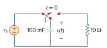
Figure 16.41
For Prob. 16.18.
Expert Solution & Answer

Trending nowThis is a popular solution!

Students have asked these similar questions
16.32 Design a V/F converter as shown in Fig. 16.64 so that fo = 2.5 kHz at v₁ = 5 V. The input voltage v₁ can
vary between 10 mV and 10 V. Assume VDD = - Vss = 5 V.
Vss=-5 V
**
+5 V
R₂
-5 V
R₂
C3
0.1 μF
Rc
H
Rin
www
HHII
Rhias
www
Cref
Vref
-5 V
1
2
3
4
5
6
7
9400 V/F
Cint
не
14
13
12
11
10
9
8
+ VDD = +5 V
NC
R₁
C4
0.01 μF
R₁
VO2
ƒ/2
Vol
fo
VDD = +5 V
16.19 Using Fig. 16.53, design a problem to help other
end students better understand circuit analysis in the
s-domain with circuits that have dependent sources.
ki
R
+
L
C
vo
vs
+,
ele
Problem 16.024 - Current through inductor
The switch in the given circuit has been closed for a long time but is opened at t= 0. Determine (t) for t> 0. Assume v₁ = 40 V.
i(t)
H
m
Vi
(+
F
=
292
ww
t=0
The value of (t) = AeBt C(Dt-E)u(t) A
where A
B=
C = (Click to select) D =
and E=
Chapter 16 Solutions
Fundamentals of Electric Circuits
Ch. 16.2 - Determine vo(t) in the circuit of Fig. 16.6,...Ch. 16.2 - Prob. 2PPCh. 16.2 - Prob. 3PPCh. 16.3 - For the circuit shown in Fig. 16.12 with the same...Ch. 16.3 - Prob. 5PPCh. 16.3 - The initial energy in the circuit of Fig. 16.17 is...Ch. 16.4 - Prob. 7PPCh. 16.4 - Prob. 8PPCh. 16.4 - Prob. 9PPCh. 16.5 - Obtain the state variable model for the circuit...
Ch. 16.5 - Prob. 11PPCh. 16.5 - Prob. 12PPCh. 16.6 - For what value of is the circuit in Fig. 16.29...Ch. 16.6 - Prob. 14PPCh. 16.6 - Prob. 15PPCh. 16.6 - Synthesize the function Vo(s)Vin=2ss2+6s+10 using...Ch. 16 - Prob. 1RQCh. 16 - The current through an RL series circuit with...Ch. 16 - Prob. 3RQCh. 16 - Prob. 4RQCh. 16 - Prob. 5RQCh. 16 - Prob. 6RQCh. 16 - Prob. 7RQCh. 16 - Prob. 8RQCh. 16 - Prob. 9RQCh. 16 - Prob. 10RQCh. 16 - The current in an RLC circuit is described by...Ch. 16 - The differential equation that describes the...Ch. 16 - Prob. 3PCh. 16 - If R = 20 , L = 0.6 H, what value of C will make...Ch. 16 - The responses of a series RLC circuit are vc(t) =...Ch. 16 - Prob. 6PCh. 16 - Prob. 7PCh. 16 - Prob. 8PCh. 16 - Prob. 9PCh. 16 - The step responses of a series RLC circuit are Vc...Ch. 16 - The step response of a parallel RLC circuit is v =...Ch. 16 - Prob. 12PCh. 16 - Prob. 13PCh. 16 - Prob. 14PCh. 16 - For the circuit in Fig. 16.38. calculate the value...Ch. 16 - The capacitor in the circuit of Fig. 16.39 is...Ch. 16 - If is(t) = 7.5e2t u(t) A in the circuit shown in...Ch. 16 - Find v(t), t 0 in the circuit of Fig. 16.41. Let...Ch. 16 - The switch in Fig. 16.42 moves from position A to...Ch. 16 - Find i(t) for t 0 in the circuit of Fig. 16.43.Ch. 16 - In the circuit of Fig. 16.44, the switch moves...Ch. 16 - Find the voltage across the capacitor as a...Ch. 16 - Obtain v (t) for t 0 in the circuit of Fig....Ch. 16 - The switch in the circuit of Fig. 16.47 has been...Ch. 16 - Calculate v(t) for t 0 in the circuit of Fig....Ch. 16 - Prob. 26PCh. 16 - Find v (t) for t 0 in the circuit in Fig. 16.50.Ch. 16 - For the circuit in Fig. 16.51, find v(t) for t 0.Ch. 16 - Prob. 29PCh. 16 - Find vo(t), for all t 0, in the circuit of Fig....Ch. 16 - Prob. 31PCh. 16 - For the network in Fig. 16.55, solve for i(t) for...Ch. 16 - Using Fig. 16.56, design a problem to help other...Ch. 16 - Prob. 34PCh. 16 - Prob. 35PCh. 16 - Prob. 36PCh. 16 - Prob. 37PCh. 16 - The switch in the circuit of Fig. 16.61 is moved...Ch. 16 - Prob. 39PCh. 16 - Prob. 40PCh. 16 - Prob. 41PCh. 16 - Prob. 42PCh. 16 - Prob. 43PCh. 16 - Prob. 44PCh. 16 - Find v(t) for t 0 in the circuit in Fig. 16.68.Ch. 16 - Prob. 46PCh. 16 - Determine io(t) in the network shown in Fig....Ch. 16 - Prob. 48PCh. 16 - Find i0(t) for t 0 in the circuit in Fig. 16.72....Ch. 16 - Prob. 50PCh. 16 - In the circuit of Fig. 16.74, find i(t) for t 0.Ch. 16 - Prob. 52PCh. 16 - In the circuit of Fig. 16.76, the switch has been...Ch. 16 - Prob. 54PCh. 16 - Prob. 55PCh. 16 - Calculate io(t) for t 0 in the network of Fig....Ch. 16 - Prob. 57PCh. 16 - Prob. 58PCh. 16 - Find vo(t) in the circuit of Fig. 16.82 if vx(0) =...Ch. 16 - Prob. 60PCh. 16 - Prob. 61PCh. 16 - Using Fig. 16.85, design a problem to help other...Ch. 16 - Consider the parallel RLC circuit of Fig. 16.86....Ch. 16 - The switch in Fig. 16.87 moves from position 1 to...Ch. 16 - For the RLC circuit shown in Fig. 16.88, find the...Ch. 16 - For the op amp circuit in Fig. 16.89, find v0(t)...Ch. 16 - Given the op amp circuit in Fig. 16.90, if v1(0+)...Ch. 16 - Prob. 68PCh. 16 - Prob. 69PCh. 16 - Using Fig. 16.93, design a problem to help other...Ch. 16 - Prob. 71PCh. 16 - The transfer function of a system is H(s)=s23s+1...Ch. 16 - Prob. 73PCh. 16 - Design a problem to help other students better...Ch. 16 - Prob. 75PCh. 16 - For the circuit in Fig. 16.95, find H(s) =...Ch. 16 - Obtain the transfer function H(s) = VoVs for the...Ch. 16 - Prob. 78PCh. 16 - For the circuit in Fig. 16.97, find: (a) I1/Vs (b)...Ch. 16 - Refer to the network in Fig. 16.98. Find the...Ch. 16 - Prob. 81PCh. 16 - Prob. 82PCh. 16 - Refer to the RL circuit in Fig. 16.101. Find: (a)...Ch. 16 - A parallel RL circuit has R = 4 and L = 1 H. The...Ch. 16 - Prob. 85PCh. 16 - Prob. 86PCh. 16 - Prob. 87PCh. 16 - Prob. 88PCh. 16 - Develop the state equations for the circuit shown...Ch. 16 - Prob. 90PCh. 16 - Prob. 91PCh. 16 - Prob. 92PCh. 16 - Prob. 93PCh. 16 - Prob. 94PCh. 16 - Prob. 95PCh. 16 - Prob. 96PCh. 16 - A system is formed by cascading two systems as...Ch. 16 - Determine whether the op amp circuit in Fig....Ch. 16 - It is desired realize the transfer function...Ch. 16 - Prob. 100PCh. 16 - Prob. 101PCh. 16 - Synthesize the transfer function...Ch. 16 - Prob. 103CPCh. 16 - Prob. 104CPCh. 16 - Prob. 105CP
Knowledge Booster


Learn more about
Need a deep-dive on the concept behind this application? Look no further. Learn more about this topic, electrical-engineering and related others by exploring similar questions and additional content below.Similar questions
- 16.33 Design an F/V converter as shown in Fig. 16.67 so that Vo = 2.5 V at fin can vary between 0 and 20 kHz. Assume VDD -Vss = 5 V. Dz 6.2 V R₁ 10 ΚΩ R₂ C₁ 0.001 µF Offset adjustment R₂ Bias www == Cref Rbias Iin Vss +11 Ref out Vref 1 2 3 5 4 9400 F/V 11 6 14 7 12 Rint FIGURE 16.67 TelCom 9400 converter connected as an F/V converter = 10 kHz. The input frequency fin VDD 10-15 V C4 Vo output Cint VIarrow_forwardFind V, (s) in the circuit shown in Fig. 16.49. 0.25 H 102 V, Eww 3V, 0.2 F Se-ut)Varrow_forward16.22 Design a monostable multivibrator as in Fig. 16.45(a) so that p = 2 ms. Assume Vcc = 15 V. Trigger input V V Vo Waveshaping network R₂ D₁ Output Vcc 8 2 Trigger NE/SE- 555 3 Output Reset Discharge 7 Threshold 6 Control 1 vc(1) C C₁ 0.01 μF -+Vcc + C3 10 μFarrow_forward
- 3. Convert the following expressions in Product-of-Maxterm form: a) F=XY+Y'Z b) F= (A'+B') (B+C) (A+B'+C')arrow_forwardSimplify the following expressions to (1) sum-of-products and (2) products-of- sums: (a) xz + yz + yz + xy (b) (c) (A + C + D)(A + B + D)(Ā+ B + D) (A + B + C) (d) ABC + ABD + BCD ACD+CD+ AB + ABCDarrow_forwardGiven: F(a, b, c) = abc + b a. Express F as a minterm expansion. (Use m-notation.) b. Express F as a maxterm expansion. (Use M-notation.)arrow_forward
- Problem 16.027 - Voltage across capacitor Find (t) for t> 0 in the given circuit. Assume /= 8u(t) A. t=0 1 H m 4.5 A 10 92 + v=4F 5Ω I The value of v(t) = [A + (B)e Ct+ (D)e-4.949tju(t) V where A = 1667 X B = -1683.630 X = 0.07576 X and D = 16.680 Xarrow_forward3 Consider the parallel RLC circuit of Fig. 16.57. Find v(t) and i(t) given that v(0) = 5 and i(0) = -2 A. using mesh 4u(1) A 1092 www 4 H -19 Farrow_forwardUsing Fig. 16.56, design a problem to help other students understand how to use Thevenin's theorem (in the s-domain) to aid in circuit analysis. R1 L ll + C R2 v(t) (+ vo -arrow_forward
- 16.69 Find Ij(s) and I2(s) in the circuit of Fig. 16.92. 1 H 2 H V 2 H i2 ll ll 10e-3'u(t) V 1Ωarrow_forwardPRACTICE PROBLEM 16.2 Find vo(t) in the circuit shown in Fig. 16.9. Note that, since the voltage input is multiplied by u(t), the voltage source is a short for all t < 0 and i < (0) = 0. Answer: (e-2¹+e-¹/3)u(t) V. e-21 u(t) V Figure 16.9 192 ww ww 2H 222 For Practice Prob. 16.2. +arrow_forward16.34 Solve for the mesh currents in the circuit of Fig. 16.57. You may leave your results in the s-domain. 4 Q 20u(t) V (+ H ( 12 1Harrow_forward
arrow_back_ios
SEE MORE QUESTIONS
arrow_forward_ios
Recommended textbooks for you
 Introductory Circuit Analysis (13th Edition)Electrical EngineeringISBN:9780133923605Author:Robert L. BoylestadPublisher:PEARSON
 Delmar's Standard Textbook Of ElectricityElectrical EngineeringISBN:9781337900348Author:Stephen L. HermanPublisher:Cengage Learning
 Programmable Logic ControllersElectrical EngineeringISBN:9780073373843Author:Frank D. PetruzellaPublisher:McGraw-Hill Education
 Fundamentals of Electric CircuitsElectrical EngineeringISBN:9780078028229Author:Charles K Alexander, Matthew SadikuPublisher:McGraw-Hill Education
 Electric Circuits. (11th Edition)Electrical EngineeringISBN:9780134746968Author:James W. Nilsson, Susan RiedelPublisher:PEARSON
 Engineering ElectromagneticsElectrical EngineeringISBN:9780078028151Author:Hayt, William H. (william Hart), Jr, BUCK, John A.Publisher:Mcgraw-hill Education,
Introductory Circuit Analysis (13th Edition)
Electrical Engineering
ISBN:9780133923605
Author:Robert L. Boylestad
Publisher:PEARSON
Delmar's Standard Textbook Of Electricity
Electrical Engineering
ISBN:9781337900348
Author:Stephen L. Herman
Publisher:Cengage Learning
Programmable Logic Controllers
Electrical Engineering
ISBN:9780073373843
Author:Frank D. Petruzella
Publisher:McGraw-Hill Education
Fundamentals of Electric Circuits
Electrical Engineering
ISBN:9780078028229
Author:Charles K Alexander, Matthew Sadiku
Publisher:McGraw-Hill Education
Electric Circuits. (11th Edition)
Electrical Engineering
ISBN:9780134746968
Author:James W. Nilsson, Susan Riedel
Publisher:PEARSON
Engineering Electromagnetics
Electrical Engineering
ISBN:9780078028151
Author:Hayt, William H. (william Hart), Jr, BUCK, John A.
Publisher:Mcgraw-hill Education,
Systems and Simulation - Lecture 3: Modelling of Mechanical systems; Author: bioMechatronics Lab;https://www.youtube.com/watch?v=fMcDdyoC9mA;License: Standard Youtube License