
Videos
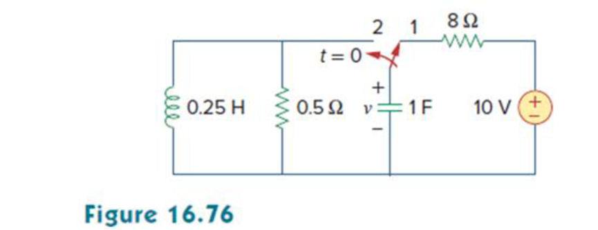
In the circuit of Fig. 16.76, the switch has been in position 1 for a long time but moved to position 2 at t = 0. Find:
- (a) v(0+), dv(0+)/dt
- (b) v(t) for t ≥ 0.
a.
Find the value of
Answer to Problem 53P
The value of
Explanation of Solution
Given data:
Refer to Figure 16.76 in the textbook.
The switch is in position 1 for a long time and moved to position 2 at
Calculation:
The given circuit is redrawn as shown in Figure 1.
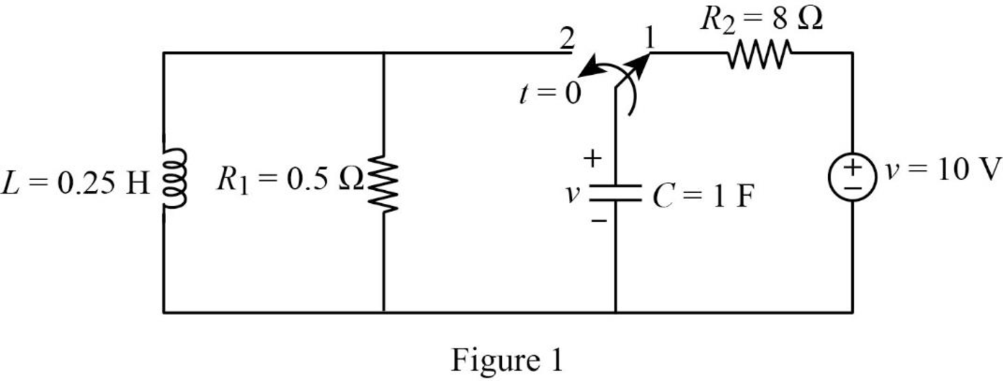
For a DC circuit, at steady state condition when the switch is in position ‘1’at time
Now, the Figure 1 is reduced as shown in Figure 2.
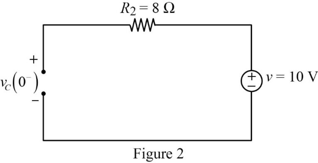
Refer to Figure 2, the voltage across the resistor is same as the voltage across the capacitor which is the source voltage.
The current through inductor and voltage across capacitor is always continuous so that,
When the switch is in position ‘2’, the Figure 1 is reduced as shown in Figure 3.
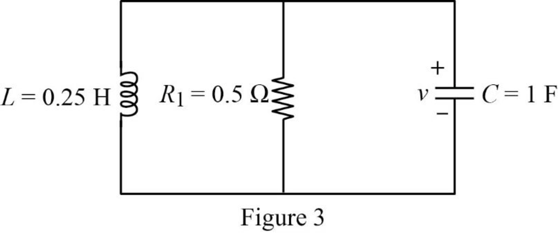
Refer to Figure 3, the capacitor, resistor and inductor are connected in parallel. For the parallel connection the voltage is same. In Figure 3, the magnitude of voltage is in opposite direction.
Apply Kirchhoff’s current law for Figure 3.
Substitute
Write an expression to calculate the current through resistor.
Substitute
Substitute
Substitute
At time
Rearrange the above equation to find
Substitute
Conclusion:
Thus, the value of
b.
Find the expression of voltage
Answer to Problem 53P
The expression of voltage
Explanation of Solution
Formula used:
Write a general expression to calculate the impedance of a resistor in s-domain.
Here,
Write a general expression to calculate the impedance of an inductor in s-domain.
Here,
Write a general expression to calculate the impedance of a capacitor in s-domain.
Here,
Calculation:
Substitute
Substitute
Substitute
Using element transformation methods with initial conditions convert the Figure 3 into s-domain.
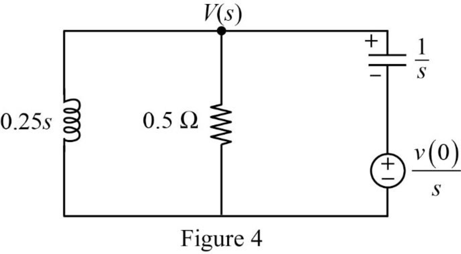
Apply nodal analysis at node
Substitute
Simplify the above equation to find
From the above equation , the characteristic equation is
Write a general expression to calculate the roots of quadratic equation
Comparing the equation (6) with the equation
Substitute
Simplify the above equation to find
Substitute the roots of characteristic equation in equation (5) to find
Take partial fraction for above equation.
The equation (8) can also be written as follows:
Simplify the above equation as follows:
Substitute
Simplify the above equation to find
Substitute
Simplify the above equation to find
Substitute
Take inverse Laplace transform for above equation to find
Simplify the above equation to find
Conclusion:
Thus, the expression of voltage
Want to see more full solutions like this?
Chapter 16 Solutions
Fundamentals of Electric Circuits


- The systems input output equation is in the picture find the zero state response yzs(t) to x(t) = u(t) (unit step)arrow_forwardKnow how to analyze a circuit in the s domain and be ableto transform an s-domain solution to the time domain Using the circuit in verify that i2 reaches a peak value of 481.13 mA at t=549.31 ms.arrow_forwardUSE THE CIRCUITS IN THE S-DOMAIN The parameter values for the circuit in are as follows: R=1kΩ,L=12.5H,C=2μF, and Idc=30mA. I need to find vo(t) for t≥0, Find io(t) for t≥0.3. Does your solution for io(t) make sense when t=0?arrow_forward
- The following differential equations, r (t) input and y (t) output, refer to linear, time-invariant systems. Find the Y (s) / R (s) transfer function for each system.arrow_forwardSignal and system The mathematical model of a system is y" (t) + ay'(t) + by(t) = x" (t) + cx(t) where a=-3, b=-3 and c=-3. 1) Find zeros and poles of the system. 2) Show them onto the S-Plane (the complex plane) 3) Discuss the BIBO stability of the system.arrow_forwardfor H(s) = (s + 1)/(s + 4)2 find the system response to the input u(t) aka the unit step functionarrow_forward
- The step response of an continuous-time LTI system is given by (1 - e-t)u(t). For a certain unknown input x(t) , the output y(t) is observed to be (2 - 3e-t + e-3t)u(t). a) Find the input x(t) as a function of time. b) Is this system BIBO stable.arrow_forwardExplain the following: 1) LTI Systems2) Frequency response of LTI Systems 3) LTI System Eigen-function and Eigen-valuearrow_forwardThe step response of a time LTI system continuous is given by (1-e-t )u(t). For some unknown input x(t), the output y(t) is observed to be (2-3e-t +e-3t ) u(t). Find the input x(t).arrow_forward
- For the RLC circuit given in the figure, we will find state variables such that the state equations of the system x=Ax+Bu , y=cx+du can be written in the form . Note: Accept the system output as ic.arrow_forwardLet A[n] = u[n] B[n] = 3nu[n] discrete functions (u[n] step function) Get C[n] = A[n]* A[n] And D[m] =A[n] *B[n] * denotes convolutionarrow_forwardAdvanced Math Find the impulse response, h(t) given: y'''' - y = f(t) or y"" - y = delta dirac answer is belowarrow_forward
 Introductory Circuit Analysis (13th Edition)Electrical EngineeringISBN:9780133923605Author:Robert L. BoylestadPublisher:PEARSON
 Delmar's Standard Textbook Of ElectricityElectrical EngineeringISBN:9781337900348Author:Stephen L. HermanPublisher:Cengage Learning
 Programmable Logic ControllersElectrical EngineeringISBN:9780073373843Author:Frank D. PetruzellaPublisher:McGraw-Hill Education
 Fundamentals of Electric CircuitsElectrical EngineeringISBN:9780078028229Author:Charles K Alexander, Matthew SadikuPublisher:McGraw-Hill Education
 Electric Circuits. (11th Edition)Electrical EngineeringISBN:9780134746968Author:James W. Nilsson, Susan RiedelPublisher:PEARSON
 Engineering ElectromagneticsElectrical EngineeringISBN:9780078028151Author:Hayt, William H. (william Hart), Jr, BUCK, John A.Publisher:Mcgraw-hill Education,