
Videos
Synthesize the transfer function
using the topology of Fig. 16.111. Let Y1 = 1/R1, Y2 = 1/R2, Y3 = sC1, Y4 = sC2. Choose R1 = 1 kΩ and determine C1, C2, and R2.
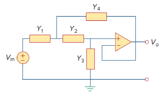
Figure 16.111
Want to see the full answer?
Check out a sample textbook solution
Chapter 16 Solutions
Fundamentals of Electric Circuits


- Vi(t). CCT1 R₁ R₁ CCT2 Li 00000 00000 L₁ 00000 L₂ R₂ R Rf OA1 OA2 R ip#, Vp# in#, Vn# Ra Ra CCT3 OA3 Ro + OA# Ro Vo# vo(t) Derive the total CCT transfer function from Vi(s) to Vo(s) by combining CCT1, CCT2, and CCT3.arrow_forwardTRY THIS : 16.1 Design a Full subtractor using 4 to 1 multiplexerarrow_forwardUsing 16’s complement representation; perform subtraction X-Y and Y-XWhere X= 10111100Y=10101011arrow_forward
- 16.20 a. Design a VCO as shown in Fig. 16.43(c) that has a nominal frequency of fo = 10 kHz. Assume Vcc = 15 V. D b. Calculate the modulation in the output frequencies if VCN is varied by ±10%. +Vcc R₂ VCN=Vcs+Ven Ven C3 R₂ C₂ 0.001 μF 5 R₁ NE/SE- 566 VCO C₁ 4 vo 1 www. 3—um Voarrow_forward16.19 Using Fig. 16.53, design a problem to help other end students better understand circuit analysis in the s-domain with circuits that have dependent sources. ki R + L C vo vs +, elearrow_forward58 VPN l a/y.Jv,1 2_541158988879967... s+100 Integrator? Integratort Transler Fond Figure 3-7 7. Calculate the ess as ess = lim sE(s) = lim s- - R(s) 1+G(s) S-0arrow_forward
- There is a translational mechanical system given as in figure 1 below. Transfer function for X(s) and transfer function for system 2 is given as X(s) _ 4 3s2 +4.15s+6.75 system 1 is given as F(s) F(s) 4 2s2+2.12s+4.5 6.75 N/m 4.5 N/m 9 N-s/m 5 N-s/m 3 kg 2 kg System 1 System 2 Figure 1: Translational Mechanical System a) Determine the system type. Answer: 0000arrow_forward10 POIIS For the electrical network system below, find the transfer function VV. Use the following values. R1 = 2+C L = 4+a R2 = 3 C = 5+b 2 5 7 where a b: For reference, the 1st digit of your student number is the leftmost number in your student number. Indicate your student number when solving problems. R1 R2 v(1) C i2(1)arrow_forward260-dt-content-rid-8556654_1/courses/926578_2202_022 = تمي يز B عرض الصفحة | A قراءة بصوت عال | V رسم Page 6 of 12 z2+1.7z Q.7 A digital causal system is described by the transfer function H(z) z2-2.8z+0.8 (a) Plot the z-plane poles and zeros and comment on the system stability. (b) Evaluate the first two sample values of the impulse response. (c) Suppose the input to the digital system is given by: x[n] = 8[n] – 8[n – 3] Determine the output of the digital system for the first two sample values.arrow_forward
- Use the equivalent transformation of block diagrams to find transfer function represented by the following block diagram: R(s) G₁ ITU G3 + X(s) G₂ X(s) R(S) of the systemarrow_forward3. Convert the following expressions in Product-of-Maxterm form: a) F=XY+Y'Z b) F= (A'+B') (B+C) (A+B'+C')arrow_forward3. Obtain the transfer functions XI (s)/U(s) and X2(s)/U(s) of the mechanical system shown in Figure 11 ky www D O 1112 ww byarrow_forward
 Introductory Circuit Analysis (13th Edition)Electrical EngineeringISBN:9780133923605Author:Robert L. BoylestadPublisher:PEARSON
 Delmar's Standard Textbook Of ElectricityElectrical EngineeringISBN:9781337900348Author:Stephen L. HermanPublisher:Cengage Learning
 Programmable Logic ControllersElectrical EngineeringISBN:9780073373843Author:Frank D. PetruzellaPublisher:McGraw-Hill Education
 Fundamentals of Electric CircuitsElectrical EngineeringISBN:9780078028229Author:Charles K Alexander, Matthew SadikuPublisher:McGraw-Hill Education
 Electric Circuits. (11th Edition)Electrical EngineeringISBN:9780134746968Author:James W. Nilsson, Susan RiedelPublisher:PEARSON
 Engineering ElectromagneticsElectrical EngineeringISBN:9780078028151Author:Hayt, William H. (william Hart), Jr, BUCK, John A.Publisher:Mcgraw-hill Education,