
Fundamentals of Electric Circuits
6th Edition
ISBN: 9780078028229
Author: Charles K Alexander, Matthew Sadiku
Publisher: McGraw-Hill Education
expand_more
expand_more
format_list_bulleted
Videos
Textbook Question
Chapter 16, Problem 19P
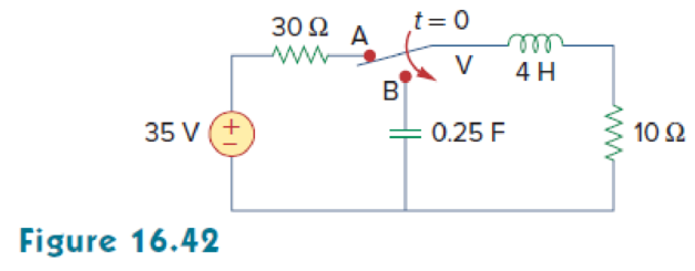
The switch in Fig. 16.42 moves from position A to position B at t = 0 (please note that the switch must connect to point B before it breaks the connection at A, a make before break switch). Find v (t) for t > 0.
Expert Solution & Answer
Want to see the full answer?
Check out a sample textbook solution
Students have asked these similar questions
Q2
Obtain the state model
ÿ = -a1Ÿ – a2Ỷ – aoY + u(t)
...
%|
Y (t) = b1Ÿ + b1Ỷ + boY
Find both the minterm and maxterm expansion for the function using algebraic manipulations:f(A,B,C,D)=(A+B+D')(A'+C)(C+D)
Save Anower
Design a combinational circuit that accepts two numbers: A and B. It adds them if they are base-11 and subtracts
them if they are BCD. If the result of addition or subtraction operations has MSB=1, the circuit must encode B into
fewer bits; otherwise, it must decode A into more bits.
(Handwriting solution is needed: include this in your pdf file)
Chapter 16 Solutions
Fundamentals of Electric Circuits
Ch. 16.2 - Determine vo(t) in the circuit of Fig. 16.6,...Ch. 16.2 - Prob. 2PPCh. 16.2 - Prob. 3PPCh. 16.3 - For the circuit shown in Fig. 16.12 with the same...Ch. 16.3 - Prob. 5PPCh. 16.3 - The initial energy in the circuit of Fig. 16.17 is...Ch. 16.4 - Prob. 7PPCh. 16.4 - Prob. 8PPCh. 16.4 - Prob. 9PPCh. 16.5 - Obtain the state variable model for the circuit...
Ch. 16.5 - Prob. 11PPCh. 16.5 - Prob. 12PPCh. 16.6 - For what value of is the circuit in Fig. 16.29...Ch. 16.6 - Prob. 14PPCh. 16.6 - Prob. 15PPCh. 16.6 - Synthesize the function Vo(s)Vin=2ss2+6s+10 using...Ch. 16 - Prob. 1RQCh. 16 - The current through an RL series circuit with...Ch. 16 - Prob. 3RQCh. 16 - Prob. 4RQCh. 16 - Prob. 5RQCh. 16 - Prob. 6RQCh. 16 - Prob. 7RQCh. 16 - Prob. 8RQCh. 16 - Prob. 9RQCh. 16 - Prob. 10RQCh. 16 - The current in an RLC circuit is described by...Ch. 16 - The differential equation that describes the...Ch. 16 - Prob. 3PCh. 16 - If R = 20 , L = 0.6 H, what value of C will make...Ch. 16 - The responses of a series RLC circuit are vc(t) =...Ch. 16 - Prob. 6PCh. 16 - Prob. 7PCh. 16 - Prob. 8PCh. 16 - Prob. 9PCh. 16 - The step responses of a series RLC circuit are Vc...Ch. 16 - The step response of a parallel RLC circuit is v =...Ch. 16 - Prob. 12PCh. 16 - Prob. 13PCh. 16 - Prob. 14PCh. 16 - For the circuit in Fig. 16.38. calculate the value...Ch. 16 - The capacitor in the circuit of Fig. 16.39 is...Ch. 16 - If is(t) = 7.5e2t u(t) A in the circuit shown in...Ch. 16 - Find v(t), t 0 in the circuit of Fig. 16.41. Let...Ch. 16 - The switch in Fig. 16.42 moves from position A to...Ch. 16 - Find i(t) for t 0 in the circuit of Fig. 16.43.Ch. 16 - In the circuit of Fig. 16.44, the switch moves...Ch. 16 - Find the voltage across the capacitor as a...Ch. 16 - Obtain v (t) for t 0 in the circuit of Fig....Ch. 16 - The switch in the circuit of Fig. 16.47 has been...Ch. 16 - Calculate v(t) for t 0 in the circuit of Fig....Ch. 16 - Prob. 26PCh. 16 - Find v (t) for t 0 in the circuit in Fig. 16.50.Ch. 16 - For the circuit in Fig. 16.51, find v(t) for t 0.Ch. 16 - Prob. 29PCh. 16 - Find vo(t), for all t 0, in the circuit of Fig....Ch. 16 - Prob. 31PCh. 16 - For the network in Fig. 16.55, solve for i(t) for...Ch. 16 - Using Fig. 16.56, design a problem to help other...Ch. 16 - Prob. 34PCh. 16 - Prob. 35PCh. 16 - Prob. 36PCh. 16 - Prob. 37PCh. 16 - The switch in the circuit of Fig. 16.61 is moved...Ch. 16 - Prob. 39PCh. 16 - Prob. 40PCh. 16 - Prob. 41PCh. 16 - Prob. 42PCh. 16 - Prob. 43PCh. 16 - Prob. 44PCh. 16 - Find v(t) for t 0 in the circuit in Fig. 16.68.Ch. 16 - Prob. 46PCh. 16 - Determine io(t) in the network shown in Fig....Ch. 16 - Prob. 48PCh. 16 - Find i0(t) for t 0 in the circuit in Fig. 16.72....Ch. 16 - Prob. 50PCh. 16 - In the circuit of Fig. 16.74, find i(t) for t 0.Ch. 16 - Prob. 52PCh. 16 - In the circuit of Fig. 16.76, the switch has been...Ch. 16 - Prob. 54PCh. 16 - Prob. 55PCh. 16 - Calculate io(t) for t 0 in the network of Fig....Ch. 16 - Prob. 57PCh. 16 - Prob. 58PCh. 16 - Find vo(t) in the circuit of Fig. 16.82 if vx(0) =...Ch. 16 - Prob. 60PCh. 16 - Prob. 61PCh. 16 - Using Fig. 16.85, design a problem to help other...Ch. 16 - Consider the parallel RLC circuit of Fig. 16.86....Ch. 16 - The switch in Fig. 16.87 moves from position 1 to...Ch. 16 - For the RLC circuit shown in Fig. 16.88, find the...Ch. 16 - For the op amp circuit in Fig. 16.89, find v0(t)...Ch. 16 - Given the op amp circuit in Fig. 16.90, if v1(0+)...Ch. 16 - Prob. 68PCh. 16 - Prob. 69PCh. 16 - Using Fig. 16.93, design a problem to help other...Ch. 16 - Prob. 71PCh. 16 - The transfer function of a system is H(s)=s23s+1...Ch. 16 - Prob. 73PCh. 16 - Design a problem to help other students better...Ch. 16 - Prob. 75PCh. 16 - For the circuit in Fig. 16.95, find H(s) =...Ch. 16 - Obtain the transfer function H(s) = VoVs for the...Ch. 16 - Prob. 78PCh. 16 - For the circuit in Fig. 16.97, find: (a) I1/Vs (b)...Ch. 16 - Refer to the network in Fig. 16.98. Find the...Ch. 16 - Prob. 81PCh. 16 - Prob. 82PCh. 16 - Refer to the RL circuit in Fig. 16.101. Find: (a)...Ch. 16 - A parallel RL circuit has R = 4 and L = 1 H. The...Ch. 16 - Prob. 85PCh. 16 - Prob. 86PCh. 16 - Prob. 87PCh. 16 - Prob. 88PCh. 16 - Develop the state equations for the circuit shown...Ch. 16 - Prob. 90PCh. 16 - Prob. 91PCh. 16 - Prob. 92PCh. 16 - Prob. 93PCh. 16 - Prob. 94PCh. 16 - Prob. 95PCh. 16 - Prob. 96PCh. 16 - A system is formed by cascading two systems as...Ch. 16 - Determine whether the op amp circuit in Fig....Ch. 16 - It is desired realize the transfer function...Ch. 16 - Prob. 100PCh. 16 - Prob. 101PCh. 16 - Synthesize the transfer function...Ch. 16 - Prob. 103CPCh. 16 - Prob. 104CPCh. 16 - Prob. 105CP
Knowledge Booster


Learn more about
Need a deep-dive on the concept behind this application? Look no further. Learn more about this topic, electrical-engineering and related others by exploring similar questions and additional content below.Similar questions
- S/w testing Show the representation of minterm and maxterm for three variables (D+M) Consider function F= xy+ yz+ z, represent this function in terms of soparrow_forward7) In a 4 - variable K-Map, the cells (4,5,6, 7) can be grouped together. Select one: True Falsearrow_forward2. (a) What is the difference between a canonical form and a standard form? Are all canonical forms standard forms? Are all standard forms canonical forms? (b) Let G(A, B,C) = ĀBC + BC. Is this a standard form? Is this a canonical form? Explain how you know. (Use this expression for G for the rest of Problem 2.) (c) Draw a logic circuit diagram for G as given in part (b). (d) Write an expression for G in canonical sum of products (SOP) form (sum of minterms). Note that the second term of the expression you are given doesn't depend on A. If you are uncertain of how to handle this, try writing a truth table for this function. (e) Draw a logic circuit diagram for the canonical SOP form of G that you found in question (d). (f) Your logic circuit diagrams from parts (c) and (e) should implement the exact same function in two different ways. Which is a better solution, and why?arrow_forward
- Simplify the following logic expression F= ABC + A + ABC F = AC + A` %3D O F = A` + B F = C F = A` + C F = AC + 1 F = 1arrow_forward*57 VPN ll a /JE7,0 V O M2 9:£Y 2_541158988879967... 100 s2+20s+100 Step1 Transfer Fcn Figure 5-1 7. Calculate the e, as e = lim sE(s) = lim s R(s) S0 1+G(s)arrow_forwardSee all photos + Add to A Edit & Create v 2 Share Determine the simplified Sum-of-Product (SOP) and Product-of-Sum (POS) expression for the given expression by using Karnaugh map. Draw the simplified logic circuits. S(A,B,C, D) = AM (3,7,12,13, 14,15) D(5,6,11) 8:39 PM O Type here to search a 画 30℃ O 4) ENG 9/1/2022arrow_forward
- Simplify the following Boolean equations. Show your work and list which axiom or theorem you used in each step. Your final equation should be in minimized sum-of-products(SOP) form. X = (A'B + (C+DE')')(A'B + CD + BDE' + C + B') Please list each therom used line by line.arrow_forwardIn the following sequential circuit. There are 2 D FF (A and B), 2 inputs (x and y), and 1 output z The output and next-states equations are given A(t+1) = x′y + xA B(t+1) = x′B + xA z = B a- Draw the logic diagram of the circuit. b- List the state table for the sequential circuit. c- Draw the corresponding state diagram. Design a sequential circuit that produces “1” on its output if it detects the sequence “1001” on it’s input. The detector should keep checking for the appropriate sequence and should not reset to the initial state after it has recognized the sequence.arrow_forwardQ5) Minimize the following Boolean expression to its simplest form and also draw the circuit for minimized expression. F = ABC'D' + ABC'D + AB'C'D + ABCD + AB'CD + ABC'D' + AB'C D'arrow_forward
- A combinational logic circuit has four inputs (A,B,C, and D) and one output Z. The output is 1 iff the input has three consecutive 0's or three consecutive 1's. For example, if A=1, B=0, C=0, and D=0, then Z=1, but if A=0,B=1,C=0, and D=0, then Z=0. Design the circuit using one four-input OR gate and four three-input AND gates.arrow_forwardA combinational logic circuit has four inputs (A, B, C, and D) and one output Z. The output is 1 if and only ifthe input has three consecutive 0’s or three consecutive 1’s. For example, if A=1, B=0, C=0, and D=0, then Z = 1, but if A=0, B=1, C=0, and D=0, then Z=0.Design the circuit using one four-input OR gate and four three-input AND Gates.arrow_forwardHow can I build this circuit on Digital? The XOR logical operation has the following truth table: A | B | A XOR B---+---+---------0 | 0 | 00 | 1 | 11 | 0 | 11 | 1 | 0 That means that A XOR B is 1 (true) when either A or B are 1 (true), but not when they are both true. If you prefer, when exactly one of A or B is 1 (true). Produce a circuit in Digital that implements this operation. To solve this problem, you can only use the following Digital components: inputs and output (under Components/IO) supply voltage and ground (under Components/Wires) P- and N-Channel FET (under Components/Switches) - same behavior as PMOS and NMOS Your circuit should only have 2 inputs and 1 output. The input for A should be labeled 'A', the input for B should be labeled 'B', and the output should be labeled 'A XOR B'.arrow_forward
arrow_back_ios
SEE MORE QUESTIONS
arrow_forward_ios
Recommended textbooks for you
 Introductory Circuit Analysis (13th Edition)Electrical EngineeringISBN:9780133923605Author:Robert L. BoylestadPublisher:PEARSON
 Delmar's Standard Textbook Of ElectricityElectrical EngineeringISBN:9781337900348Author:Stephen L. HermanPublisher:Cengage Learning
 Programmable Logic ControllersElectrical EngineeringISBN:9780073373843Author:Frank D. PetruzellaPublisher:McGraw-Hill Education
 Fundamentals of Electric CircuitsElectrical EngineeringISBN:9780078028229Author:Charles K Alexander, Matthew SadikuPublisher:McGraw-Hill Education
 Electric Circuits. (11th Edition)Electrical EngineeringISBN:9780134746968Author:James W. Nilsson, Susan RiedelPublisher:PEARSON
 Engineering ElectromagneticsElectrical EngineeringISBN:9780078028151Author:Hayt, William H. (william Hart), Jr, BUCK, John A.Publisher:Mcgraw-hill Education,
Introductory Circuit Analysis (13th Edition)
Electrical Engineering
ISBN:9780133923605
Author:Robert L. Boylestad
Publisher:PEARSON
Delmar's Standard Textbook Of Electricity
Electrical Engineering
ISBN:9781337900348
Author:Stephen L. Herman
Publisher:Cengage Learning
Programmable Logic Controllers
Electrical Engineering
ISBN:9780073373843
Author:Frank D. Petruzella
Publisher:McGraw-Hill Education
Fundamentals of Electric Circuits
Electrical Engineering
ISBN:9780078028229
Author:Charles K Alexander, Matthew Sadiku
Publisher:McGraw-Hill Education
Electric Circuits. (11th Edition)
Electrical Engineering
ISBN:9780134746968
Author:James W. Nilsson, Susan Riedel
Publisher:PEARSON
Engineering Electromagnetics
Electrical Engineering
ISBN:9780078028151
Author:Hayt, William H. (william Hart), Jr, BUCK, John A.
Publisher:Mcgraw-hill Education,
Systems and Simulation - Lecture 3: Modelling of Mechanical systems; Author: bioMechatronics Lab;https://www.youtube.com/watch?v=fMcDdyoC9mA;License: Standard Youtube License