
Fundamentals of Electric Circuits
6th Edition
ISBN: 9780078028229
Author: Charles K Alexander, Matthew Sadiku
Publisher: McGraw-Hill Education
expand_more
expand_more
format_list_bulleted
Videos
Textbook Question
Chapter 16, Problem 27P
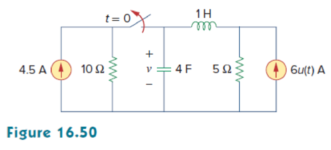
Find v (t) for t > 0 in the circuit in Fig. 16.50.
Expert Solution & Answer
Want to see the full answer?
Check out a sample textbook solution
Students have asked these similar questions
In a 4 - variable K-Map, the cells (0,5,15,10)
can be grouped together.
Select one:
True
False
Convert the following maxterms into minterms and minimize the minterms using K-map.
Y(A, B, C, D) = |
|M(2,3,8,10,12,13,14,15)
A) The probabilities for two events, C and D: P(C)=0.60, P(D)=0.40, P(CUD) =0.65
Are the events, C and D, independent in this situation? Prove it?
Chapter 16 Solutions
Fundamentals of Electric Circuits
Ch. 16.2 - Determine vo(t) in the circuit of Fig. 16.6,...Ch. 16.2 - Prob. 2PPCh. 16.2 - Prob. 3PPCh. 16.3 - For the circuit shown in Fig. 16.12 with the same...Ch. 16.3 - Prob. 5PPCh. 16.3 - The initial energy in the circuit of Fig. 16.17 is...Ch. 16.4 - Prob. 7PPCh. 16.4 - Prob. 8PPCh. 16.4 - Prob. 9PPCh. 16.5 - Obtain the state variable model for the circuit...
Ch. 16.5 - Prob. 11PPCh. 16.5 - Prob. 12PPCh. 16.6 - For what value of is the circuit in Fig. 16.29...Ch. 16.6 - Prob. 14PPCh. 16.6 - Prob. 15PPCh. 16.6 - Synthesize the function Vo(s)Vin=2ss2+6s+10 using...Ch. 16 - Prob. 1RQCh. 16 - The current through an RL series circuit with...Ch. 16 - Prob. 3RQCh. 16 - Prob. 4RQCh. 16 - Prob. 5RQCh. 16 - Prob. 6RQCh. 16 - Prob. 7RQCh. 16 - Prob. 8RQCh. 16 - Prob. 9RQCh. 16 - Prob. 10RQCh. 16 - The current in an RLC circuit is described by...Ch. 16 - The differential equation that describes the...Ch. 16 - Prob. 3PCh. 16 - If R = 20 , L = 0.6 H, what value of C will make...Ch. 16 - The responses of a series RLC circuit are vc(t) =...Ch. 16 - Prob. 6PCh. 16 - Prob. 7PCh. 16 - Prob. 8PCh. 16 - Prob. 9PCh. 16 - The step responses of a series RLC circuit are Vc...Ch. 16 - The step response of a parallel RLC circuit is v =...Ch. 16 - Prob. 12PCh. 16 - Prob. 13PCh. 16 - Prob. 14PCh. 16 - For the circuit in Fig. 16.38. calculate the value...Ch. 16 - The capacitor in the circuit of Fig. 16.39 is...Ch. 16 - If is(t) = 7.5e2t u(t) A in the circuit shown in...Ch. 16 - Find v(t), t 0 in the circuit of Fig. 16.41. Let...Ch. 16 - The switch in Fig. 16.42 moves from position A to...Ch. 16 - Find i(t) for t 0 in the circuit of Fig. 16.43.Ch. 16 - In the circuit of Fig. 16.44, the switch moves...Ch. 16 - Find the voltage across the capacitor as a...Ch. 16 - Obtain v (t) for t 0 in the circuit of Fig....Ch. 16 - The switch in the circuit of Fig. 16.47 has been...Ch. 16 - Calculate v(t) for t 0 in the circuit of Fig....Ch. 16 - Prob. 26PCh. 16 - Find v (t) for t 0 in the circuit in Fig. 16.50.Ch. 16 - For the circuit in Fig. 16.51, find v(t) for t 0.Ch. 16 - Prob. 29PCh. 16 - Find vo(t), for all t 0, in the circuit of Fig....Ch. 16 - Prob. 31PCh. 16 - For the network in Fig. 16.55, solve for i(t) for...Ch. 16 - Using Fig. 16.56, design a problem to help other...Ch. 16 - Prob. 34PCh. 16 - Prob. 35PCh. 16 - Prob. 36PCh. 16 - Prob. 37PCh. 16 - The switch in the circuit of Fig. 16.61 is moved...Ch. 16 - Prob. 39PCh. 16 - Prob. 40PCh. 16 - Prob. 41PCh. 16 - Prob. 42PCh. 16 - Prob. 43PCh. 16 - Prob. 44PCh. 16 - Find v(t) for t 0 in the circuit in Fig. 16.68.Ch. 16 - Prob. 46PCh. 16 - Determine io(t) in the network shown in Fig....Ch. 16 - Prob. 48PCh. 16 - Find i0(t) for t 0 in the circuit in Fig. 16.72....Ch. 16 - Prob. 50PCh. 16 - In the circuit of Fig. 16.74, find i(t) for t 0.Ch. 16 - Prob. 52PCh. 16 - In the circuit of Fig. 16.76, the switch has been...Ch. 16 - Prob. 54PCh. 16 - Prob. 55PCh. 16 - Calculate io(t) for t 0 in the network of Fig....Ch. 16 - Prob. 57PCh. 16 - Prob. 58PCh. 16 - Find vo(t) in the circuit of Fig. 16.82 if vx(0) =...Ch. 16 - Prob. 60PCh. 16 - Prob. 61PCh. 16 - Using Fig. 16.85, design a problem to help other...Ch. 16 - Consider the parallel RLC circuit of Fig. 16.86....Ch. 16 - The switch in Fig. 16.87 moves from position 1 to...Ch. 16 - For the RLC circuit shown in Fig. 16.88, find the...Ch. 16 - For the op amp circuit in Fig. 16.89, find v0(t)...Ch. 16 - Given the op amp circuit in Fig. 16.90, if v1(0+)...Ch. 16 - Prob. 68PCh. 16 - Prob. 69PCh. 16 - Using Fig. 16.93, design a problem to help other...Ch. 16 - Prob. 71PCh. 16 - The transfer function of a system is H(s)=s23s+1...Ch. 16 - Prob. 73PCh. 16 - Design a problem to help other students better...Ch. 16 - Prob. 75PCh. 16 - For the circuit in Fig. 16.95, find H(s) =...Ch. 16 - Obtain the transfer function H(s) = VoVs for the...Ch. 16 - Prob. 78PCh. 16 - For the circuit in Fig. 16.97, find: (a) I1/Vs (b)...Ch. 16 - Refer to the network in Fig. 16.98. Find the...Ch. 16 - Prob. 81PCh. 16 - Prob. 82PCh. 16 - Refer to the RL circuit in Fig. 16.101. Find: (a)...Ch. 16 - A parallel RL circuit has R = 4 and L = 1 H. The...Ch. 16 - Prob. 85PCh. 16 - Prob. 86PCh. 16 - Prob. 87PCh. 16 - Prob. 88PCh. 16 - Develop the state equations for the circuit shown...Ch. 16 - Prob. 90PCh. 16 - Prob. 91PCh. 16 - Prob. 92PCh. 16 - Prob. 93PCh. 16 - Prob. 94PCh. 16 - Prob. 95PCh. 16 - Prob. 96PCh. 16 - A system is formed by cascading two systems as...Ch. 16 - Determine whether the op amp circuit in Fig....Ch. 16 - It is desired realize the transfer function...Ch. 16 - Prob. 100PCh. 16 - Prob. 101PCh. 16 - Synthesize the transfer function...Ch. 16 - Prob. 103CPCh. 16 - Prob. 104CPCh. 16 - Prob. 105CP
Knowledge Booster


Learn more about
Need a deep-dive on the concept behind this application? Look no further. Learn more about this topic, electrical-engineering and related others by exploring similar questions and additional content below.Similar questions
- S/w testing Show the representation of minterm and maxterm for three variables (D+M) Consider function F= xy+ yz+ z, represent this function in terms of soparrow_forwardDESIGN A 16X1 MUX USING ONLY ONE 8X1 MUX SO AS TO SATISFY THE FUNCTION F(A,B,C,D)= SUM( 1,3,4,6,8,10,12,14 ), D IS THE MSB AND CONTROLLING FACTOR( DESIGN W.R.T. D) IMPLIMENT THE CIRCUIT USING CIRCUIT MAKER AND UPLOAD TO ELEARNING. 0785363649arrow_forwardPlease answer ASAP for like.. Please Pleasearrow_forward
- Given solution for 8 and 16arrow_forward16 7 Vcc GND Strobe S 4 DO D1 5 D2 1 D3 Data Output Y 74151 Input 15 D4 14 D5 13 D6 12 D7 S2 S So 9 10 11 Select Inputs Strobe Select Output S2 S1 So Y 1 0. Do 1- D1 D2 1 1 D3 1 D4 1 1 D5 1 1 D6 1 1 1 D7 Fig.3 IC Type 74151 8-to-1 Multiplexer 8- Use the 8-to-1 MUX of Fig.3 to realized the following function: f(A, B, C, D) Σ(0,2,5,9,10,14) (3)arrow_forwardA state model representation of 11 state variable system having 2 inputs and 4 outputs. The dimensions(rows X coloumns) of matrices A,B,C and D are given as A --> a Xa B --> b X bị C--> cX C1 D-->d X d1 Then the values of " a, b, c and d" are a =11, b=11, c=4, d=11 a =11, b=2, c=4, d=2 a =11, b=11, c=4, d=4 a =11, b=11, c=2, d=4arrow_forward
- Considering the system shown below: R(s) (s+a) (s+b) 1 S PID controller Plant G(s) G(s) a. Set-up the equations and find the value of b and gain K. b. Plot the root locus. K C(s)arrow_forwardWhich of the following is a minimum sum-of-products expression for function F(a,b.c,d,e) represented by the following K-Map: ab cde 1 1 X 1 1 1 X 1 o b'de + ab'd' + a'bce' + a'bd'e + bc'de' o b'cde + ab'd' + a'bc + bc'de' + b'c'de o bc'd'e' + a'bd + ab'c' + b'cd'e + bcd'e' o bc'd'e' + a'bd + ab'c'e + ab'de' + b'cd'e + bcd'e o bd'e' + a'bd + ab'c'e + ab'de' + b'cd'e o abd'e' + a'bd + ab'c'e + ab'c'd + b'cd'e o bd'e' + a'bd + ab'c' + b'cd'e 1. 1. 1. 1.arrow_forwardExplain the mathsarrow_forward
- AlgorithmsStudent Transportation Expenses NU has very diverse students from different places. To reach the campus, each student must go through a sequence of stations to get to campus. Assume within the ith station you can pay x; to either get to station (i + 1) or (i + 2). At CSCI-304, we want to help our colleagues minimize their expenses to campus—it would be great especially after COVID-19.Input: expenses : array listing expenses to be paid at each station to move its values are non-negatives, and it has at least 2 valuesOutput: m: the expenses of transportation to the campus Note the campus station is execludedExample: Assume the below table contains the expenses per each station Station Cost 1 2 3 4 5 6 3 6.5 2 2 8 **In Python notebook**arrow_forwardA combinational circuit has four inputs (A, B, C, D) and three outputs (X, Y, Z). XYZ represents a binary number whose value equals the number of 1’s at the input. For example if ABCD = 1011, XYZ = 011.(Step by step) 1,Construct a truth table for this circuit in terms of its inputs and outputs. 2,Find the minterm expansions for X and Y. 3,Find the maxterm expansion for Z.arrow_forwardhand written solution plz...ASAParrow_forward
arrow_back_ios
SEE MORE QUESTIONS
arrow_forward_ios
Recommended textbooks for you
 Introductory Circuit Analysis (13th Edition)Electrical EngineeringISBN:9780133923605Author:Robert L. BoylestadPublisher:PEARSON
 Delmar's Standard Textbook Of ElectricityElectrical EngineeringISBN:9781337900348Author:Stephen L. HermanPublisher:Cengage Learning
 Programmable Logic ControllersElectrical EngineeringISBN:9780073373843Author:Frank D. PetruzellaPublisher:McGraw-Hill Education
 Fundamentals of Electric CircuitsElectrical EngineeringISBN:9780078028229Author:Charles K Alexander, Matthew SadikuPublisher:McGraw-Hill Education
 Electric Circuits. (11th Edition)Electrical EngineeringISBN:9780134746968Author:James W. Nilsson, Susan RiedelPublisher:PEARSON
 Engineering ElectromagneticsElectrical EngineeringISBN:9780078028151Author:Hayt, William H. (william Hart), Jr, BUCK, John A.Publisher:Mcgraw-hill Education,
Introductory Circuit Analysis (13th Edition)
Electrical Engineering
ISBN:9780133923605
Author:Robert L. Boylestad
Publisher:PEARSON
Delmar's Standard Textbook Of Electricity
Electrical Engineering
ISBN:9781337900348
Author:Stephen L. Herman
Publisher:Cengage Learning
Programmable Logic Controllers
Electrical Engineering
ISBN:9780073373843
Author:Frank D. Petruzella
Publisher:McGraw-Hill Education
Fundamentals of Electric Circuits
Electrical Engineering
ISBN:9780078028229
Author:Charles K Alexander, Matthew Sadiku
Publisher:McGraw-Hill Education
Electric Circuits. (11th Edition)
Electrical Engineering
ISBN:9780134746968
Author:James W. Nilsson, Susan Riedel
Publisher:PEARSON
Engineering Electromagnetics
Electrical Engineering
ISBN:9780078028151
Author:Hayt, William H. (william Hart), Jr, BUCK, John A.
Publisher:Mcgraw-hill Education,
Systems and Simulation - Lecture 3: Modelling of Mechanical systems; Author: bioMechatronics Lab;https://www.youtube.com/watch?v=fMcDdyoC9mA;License: Standard Youtube License