
Fundamentals of Geotechnical Engineering (MindTap Course List)
5th Edition
ISBN: 9781305635180
Author: Braja M. Das, Nagaratnam Sivakugan
Publisher: Cengage Learning
expand_more
expand_more
format_list_bulleted
Concept explainers
Videos
Textbook Question
Chapter 15, Problem 15.21P
Determine the factor of safety against bottom heave for the braced cut described in Problem 15.18. Use Eqs. (15.66) and (15.70). For Eq. (15.70), assume the length of the cut, L = 18 m.
15.18 Refer to Figure 15.51 in which γ = 17.5 kN/m3, c = 60 kN/m2, and center-to-center spacing of struts is 5 m. Draw the earth pressure envelope and determine the strut loads at levels A, B, and C.
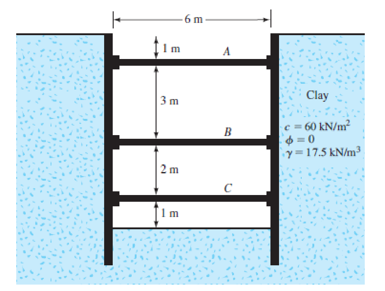
FIG. 15.51
Expert Solution & Answer

Trending nowThis is a popular solution!

Students have asked these similar questions
The braced cut of two layers of clay is shown in the figure.
1.0000
H; = 3 m; Y = 16 kN/m³ c; = 21 kN/m²
H = 3 m; Y2= 17 kN/m² ez= 22 kN/m²
H3 = 2 m; y3 = 18 kN/m³ c3= 23 kN/m?
3.0000
2.0000
Clay 1
B
The struts are located 4 m on center in the plan.
2.0000
3.0000
Determine the strut load at D.
Clay 2-
2.0000
D
1.0000
Clay 3
A
427.32 kN
424.32 kN
437.32 kN
D
227.32 kN
to
B.
Given:
γ =17.5 kN/m3c = 30 kN/m2center-to-center spacing of struts in the plan = 5 m.
Determine the factor of safety against bottom heave for the braced cut.
Use Eq. (15.20) and assume the length of the cut, L 5 18 m.
Use σ all = 170 MN/m2
Refer to the braced cut shown in the figure for
which y= 20 kN/m², o'=23°, and c' = 0.
2.0000
The struts are located 5 m on center in the plan.
Determine the strut load at A.
3.0000
3.0000
2.0000
A
1186.45 kN
В
237.29
474.26
D
1816.29
Chapter 15 Solutions
Fundamentals of Geotechnical Engineering (MindTap Course List)
Ch. 15 - Prob. 15.1PCh. 15 - Prob. 15.2PCh. 15 - Prob. 15.3PCh. 15 - Prob. 15.4PCh. 15 - Prob. 15.5PCh. 15 - Prob. 15.6PCh. 15 - Prob. 15.7PCh. 15 - Prob. 15.8PCh. 15 - Prob. 15.9PCh. 15 - Prob. 15.10P
Ch. 15 - Prob. 15.11PCh. 15 - Prob. 15.12PCh. 15 - Prob. 15.13PCh. 15 - Prob. 15.14PCh. 15 - Prob. 15.15PCh. 15 - Refer to the braced cut in Figure 15.50, for which...Ch. 15 - For the braced cut described in Problem 15.16,...Ch. 15 - Refer to Figure 15.51 in which = 17.5 kN/m3, c =...Ch. 15 - Refer to Figure 15.27a. For the braced cut, H = 6...Ch. 15 - Prob. 15.20PCh. 15 - Determine the factor of safety against bottom...Ch. 15 - Prob. 15.22PCh. 15 - The water table at a site is at 5 m below the...Ch. 15 - Prob. 15.24PCh. 15 - Prob. 15.25CTPCh. 15 - Figure 15.53 below shows a cantilever sheet pile...
Knowledge Booster


Learn more about
Need a deep-dive on the concept behind this application? Look no further. Learn more about this topic, civil-engineering and related others by exploring similar questions and additional content below.Similar questions
- The braced cut of two layers of clay is shown in the figure. 1.0000 A H; = 3 m; Y1 = 16 kN/m² c; = 21 kN/m² H; = 3 m; Y2= 17 kN/m³ cz= 22 kN/m² H3 = 2 m; Y3 = 18 kN/m² c3 = 23 kN/m² 3.0000 2.0000 Clay 1 The struts are located 4 m on center in the plan. 2.0000 Determine the strut load at C. 3.0000 - Clay 2 2.0000 1.0000 Clay 3. A 332.63 kN В 333.36 kN 332.36 kN D 322.36 kNarrow_forwardSituation 9: An 8m deep braced cuts in medium clay is shown. The unit weight = 16.5 kN/m3 and the undrained shear strength Cu = 27.8 kPa. In the plan, the struts are placed at spacing 2.4m center to center. Using Peck's Empirical pressure diagram: m 0.25H 2m В H= 8 m 0.75 H 2|m 2|m Pa = yh - 4Cu %3D 41. Compute the actual load on strut A. A. 124.57 kN C. 116.47 kN B. 153.48 kN D. 162.81 kN 42. Compute the actual load on strut B. А. 33.29 kN C. 28.42 kN B. 40.54 kN D. 35.29 kN 43. Compute the actual load on strut C. A. 127.92 kN C. 131.95 kN B. 210.38 kN D. 199.68 kNarrow_forwardThe cross section of a braced cut supporting a sheet pile installation in a clay soil is shown in the figure below. Given: H = 12 m , clay = 17.9 kN/m3 , = 0 , C = 75 kN/m2 , and the center-to-center spacing of struts in plan view , S = 3 m.arrow_forward
- Refer to the braced cut shown in Figure P15.1. Given: γ = 17 kN/m3, Φ' = 35º, and c' = 0. The struts are located at 3 m center-to-center in the plan. Draw the earth-pressure envelope and determine the strut loads at levels A, B, and C.arrow_forwardA long braced cut shown is supporting a layer of clay. Angle of fraction is 0. The struts are placed 3m center to center. a.) Determine the reaction of the strut at B. b.) Determine the section modulus of wale at B if the allowable bending stress is 0.6Fy where Fy = 250Mpaarrow_forwardRefer to Figure 15.10a. For the braced cut, given H = 8 m; H, = 3 m; y, 17.5 kN/m³; angle of friction of sand, 4' = 34°; H¸ = 5 m; y. unconfined compression strength of clay layer, q, = 55 kN/m². a. Estimate the average cohesion (cav) and average unit weight (yav) for the con- struction of the earth-pressure envelope. b. Plot the earth-pressure envelope. 18.2 kN/m³; andarrow_forward
- 4. A cut is to be made in a soil having γ = 18 kN/m3, c = 40 kPa, and φ = 15°. The cut slope makes an angle of 30°. a. If H = 6 m and θ = 15°, find the force that tend to cause sliding.b. Find the frictional force.c. Find the cohesive force.d. Find the factor of safety.e. For a factor of safety of 2.0, find the value of the critical angle along which the maximum developed cohesion occurs. f. Determine the depth of cut for a factor of safety of 2.0g. Determine the developed shear stress along the failure plane h. Determine the developed normal stress alongthe failure plane.arrow_forwardThe elevation and plan of a bracing system for an open cut in sand are shown in Figure 14.21. Using Pecks empirical pressure diagrams, determine the design strut loads. Given: sand = 18 kN/m3, ' = 38, x = 3 m, z = 1.25 m, and s = 3 m.arrow_forwardThe cross-section of a braced cut on a stiff, fissured clay (Y = 19 kN/m3, C = 40 kN/m?) is as shown in figure below. The centre to centre spacing of the struts along the length of cut is 2.5 m. The apparent earth pressure diagram for the soil is also shown below. Assuming no contribution of bottom of cut in stability of the sheeting, what are the loads in the two struts to maintain equilibrium on sheeting? %3D Н4 2 m 2 m H/2 2 m Н4 Lateral earth pressure Pa = 0.3yH 1.arrow_forward
- Question 1: The cross-section of a cantilever retaining wall is shown below. Calculate the factor of safety with regards to overturning, sliding and bearing capacity (Use Rankine). Use Yeonerete = 23.58 kN/m³ and k, =k, = 2/3 F10 0.5 m H =0.458 m Yi = 18 kN/m³ di=30° cj=0 H2=6 m 10 1.5 m = D 0.7 m H3=0.7 m C + 0.7 m + 0.7 m →l+- 2.6 m 9 kN/m³ d'½=20° cz=40 kN/m²arrow_forwardThe cantilever retaining wall shown below. The water table is 1.5 m below the ground surface (only right side). Calculate the active thrusts and passive resistances forces according to Rankine's theory and determine the factor of safety against overturning (include passive resistances). Take the unit weight of concrete as 24 kN/m and the unit weight of water is 9.81 kN/m³ (FScheek=2.00). 1 q = 50 kN/m² Stiff clay Yn= 19 kN/m³, ¢ = 24°, c= 9 kPa 1.5 m 0.4 m Loose fine sand Yn= 18 kN/m³, o = 33º, c = 0 1.0 m Ysat = 21 kN/m², = 24°, c = 9 kPa 1 m Stiff clay Stiff clay 3.3 m 2.5 m Yn = 19 kN/m', o = 24°, c=9 kPa 0.8 m 4.5 marrow_forward15.1 Refer to the braced cut shown in Figure P15.1. Given: y = 17 kN/m³, o' = 35°, and c' = 0. The struts are located at 3 m center-to-center in the plan. Draw the earth-pressure envelope and determine the strut loads at levels A, B, and C. Figure P15.1 -3.5 m- 2m 2m 1.5 m m A C Sand y = 17 kN/m² $'=35° c'=0arrow_forward
arrow_back_ios
SEE MORE QUESTIONS
arrow_forward_ios
Recommended textbooks for you
 Fundamentals of Geotechnical Engineering (MindTap...Civil EngineeringISBN:9781305635180Author:Braja M. Das, Nagaratnam SivakuganPublisher:Cengage Learning
 Principles of Foundation Engineering (MindTap Cou...Civil EngineeringISBN:9781305081550Author:Braja M. DasPublisher:Cengage Learning
 Principles of Geotechnical Engineering (MindTap C...Civil EngineeringISBN:9781305970939Author:Braja M. Das, Khaled SobhanPublisher:Cengage Learning
 Principles of Foundation Engineering (MindTap Cou...Civil EngineeringISBN:9781337705028Author:Braja M. Das, Nagaratnam SivakuganPublisher:Cengage Learning
Fundamentals of Geotechnical Engineering (MindTap...
Civil Engineering
ISBN:9781305635180
Author:Braja M. Das, Nagaratnam Sivakugan
Publisher:Cengage Learning
Principles of Foundation Engineering (MindTap Cou...
Civil Engineering
ISBN:9781305081550
Author:Braja M. Das
Publisher:Cengage Learning
Principles of Geotechnical Engineering (MindTap C...
Civil Engineering
ISBN:9781305970939
Author:Braja M. Das, Khaled Sobhan
Publisher:Cengage Learning
Principles of Foundation Engineering (MindTap Cou...
Civil Engineering
ISBN:9781337705028
Author:Braja M. Das, Nagaratnam Sivakugan
Publisher:Cengage Learning
How to build angle braces; Author: Country Living With The Harnish's;https://www.youtube.com/watch?v=3cKselS6rxY;License: Standard Youtube License