
Fundamentals of Geotechnical Engineering (MindTap Course List)
5th Edition
ISBN: 9781305635180
Author: Braja M. Das, Nagaratnam Sivakugan
Publisher: Cengage Learning
expand_more
expand_more
format_list_bulleted
Concept explainers
Videos
Textbook Question
Chapter 15, Problem 15.26CTP
Figure 15.53 below shows a cantilever sheet pile driven into a granular soil where the water table is 2 m below the top of the sand. The properties of the sand are: ϕ' = 40°, γm = 17.5 kN/m3, and γsat = 19 kN/m3. It is proposed to excavate to a depth of 6 m below the ground level. Determine the depth to which the sheet pile mast be driven, using the net lateral pressure diagram.
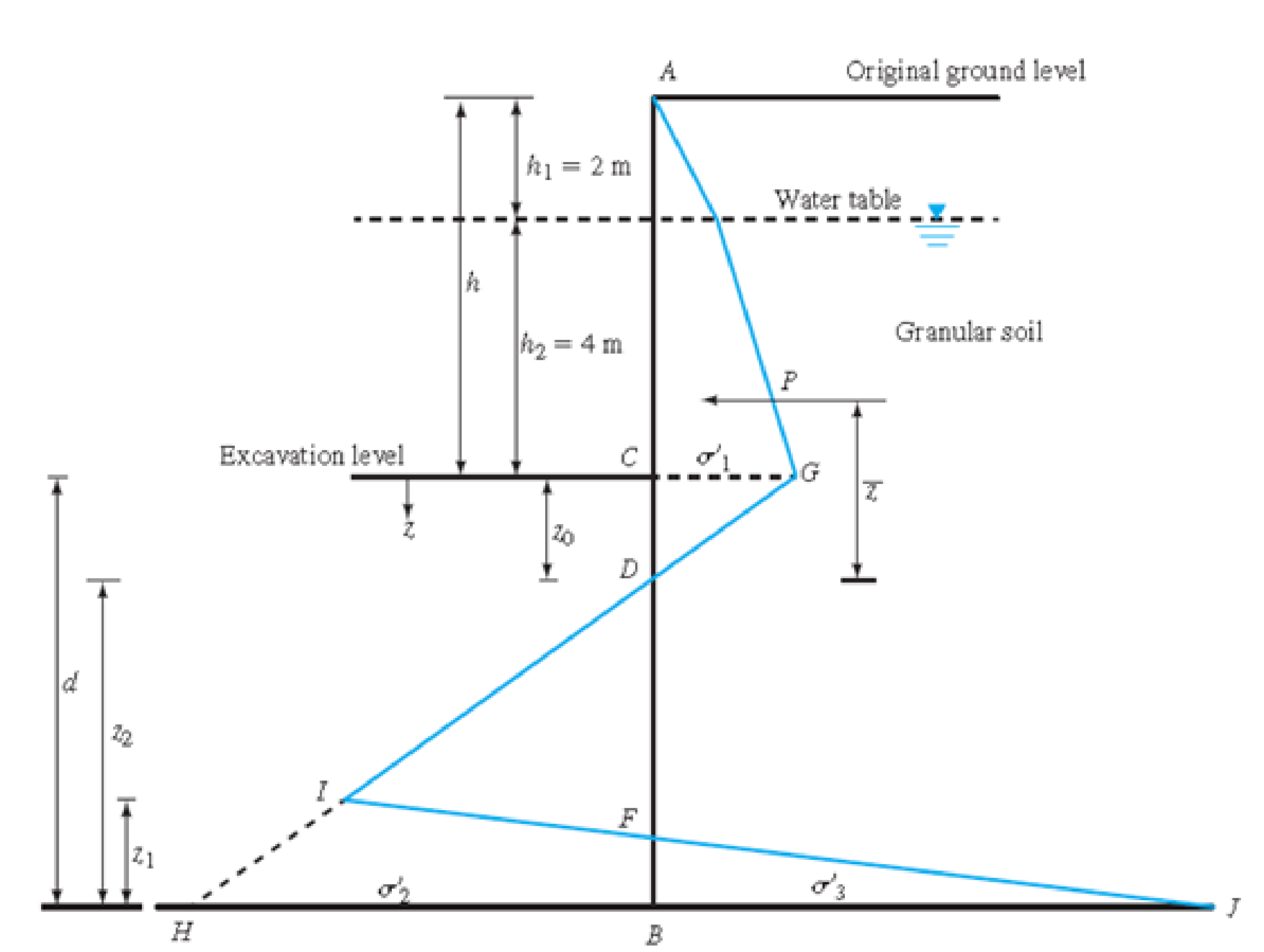
Fig. 15.53
Expert Solution & Answer

Trending nowThis is a popular solution!

Students have asked these similar questions
A 600mm diameter pile is embedded in 3 layers of dense sand at a depth of 17m. Nq = 86. The groundwater table is situated between Layers 2 and 3.
The layers have the following properties:
Layer 1: γ = 16.9 kN/m3. 3m thick.
Layer 2: γ = 17.6 kN/m3. 5.5m thick.
Layer 3: γsat = 19.65 kN/m3.
K is 0.9 and tan α = 0.37. The factor of safety is 3.0.
What is the skin friction resistance of the pile in kN?
None of the choices
1684.170
1477.156
1257.150
1322.744
866.118
Please answer this asap. For upvote. Thank you vey much.
A 600mm diameter pile is embedded in 3 layers of dense sand at a depth of 17m. Nq = 86. The groundwater table is situated between Layers 2 and 3.
The layers have the following properties:
Layer 1: γ = 16.9 kN/m3. 3m thick.
Layer 2: γ = 17.6 kN/m3. 5.5m thick.
Layer 3: γsat = 19.65 kN/m3.
K is 0.9 and tan α = 0.37. The factor of safety is 3.0.
What is the allowable axial load capacity of the pile in kN?
5476.785
1750.169
1127.606
2439.011
None of the choices
2365.846
Please answer this asap. For upvote. Thank you very much
A 600mm diameter pile is embedded in 3 layers of dense sand at a depth of 17m. Nq = 86. The groundwater table is situated between Layers 2 and 3.
The layers have the following properties:
Layer 1: γ = 16.9 kN/m3. 3m thick.
Layer 2: γ = 17.6 kN/m3. 5.5m thick.
Layer 3: γsat = 19.65 kN/m3.
K is 0.9 and tan α = 0.37. The factor of safety is 3.0.
What is the skin friction resistance of the pile in kN?
What is the skin friction resistance of the pile in kN?
None of the choices
1684.170
1477.156
1257.150
1322.744
866.118
Please answer this asap. For upvote. Thank you very much
Chapter 15 Solutions
Fundamentals of Geotechnical Engineering (MindTap Course List)
Ch. 15 - Prob. 15.1PCh. 15 - Prob. 15.2PCh. 15 - Prob. 15.3PCh. 15 - Prob. 15.4PCh. 15 - Prob. 15.5PCh. 15 - Prob. 15.6PCh. 15 - Prob. 15.7PCh. 15 - Prob. 15.8PCh. 15 - Prob. 15.9PCh. 15 - Prob. 15.10P
Ch. 15 - Prob. 15.11PCh. 15 - Prob. 15.12PCh. 15 - Prob. 15.13PCh. 15 - Prob. 15.14PCh. 15 - Prob. 15.15PCh. 15 - Refer to the braced cut in Figure 15.50, for which...Ch. 15 - For the braced cut described in Problem 15.16,...Ch. 15 - Refer to Figure 15.51 in which = 17.5 kN/m3, c =...Ch. 15 - Refer to Figure 15.27a. For the braced cut, H = 6...Ch. 15 - Prob. 15.20PCh. 15 - Determine the factor of safety against bottom...Ch. 15 - Prob. 15.22PCh. 15 - The water table at a site is at 5 m below the...Ch. 15 - Prob. 15.24PCh. 15 - Prob. 15.25CTPCh. 15 - Figure 15.53 below shows a cantilever sheet pile...
Knowledge Booster


Learn more about
Need a deep-dive on the concept behind this application? Look no further. Learn more about this topic, civil-engineering and related others by exploring similar questions and additional content below.Similar questions
- Problem #1 The figure below shows a cantilever sheet-pile wall penetrating a granular soil. Here, L₁ = 4 m, L₂ = 8 m, unit weight above water table= 16.1 kN/m³, saturated unit weight = 5 18.2 kN/m³, and friction angle of sand = 32 degrees. a. What is the theoretical depth of embedment, D? b. For a 30% increase in D, what should be the total length of the sheet piles? c. Determine the theoretical maximum moment of the sheet pile. d. If the allowable flexural stress = 170 MPa, compute the required section modulus of the sheet pile. Water table Dredge line Sand Y <=0 Sand Ysat c'=0 Sand Ysat c'=0arrow_forwardEx: The figure below is a proposed weir floor with three vertical piles. calculate the uplift pressure distribution under the floor of the weir at key point by khosla's creep flow theory? 106.00 102.25 1:5 100.50 100.00 98.50 99.25 [97.25L b = 15.75 b = 34.75 D, [93.00 93.00 b, = 15 b, = 34 91.00 b = 50.5arrow_forward1. Figure 3 shows a cantilever sheet pile wall, determine the: Sand 3 m y = 16 kN/m3 O' = 30 %3! Sand Ysat = 19 kN/m3 O' = 30 6 m Clay Ysat = 19 kN/m3 Cu = 54 kPa D %3D Figure 3 (a) Theoretical depth of embedment,arrow_forward
- Problem #1 The figure below shows a cantilever sheet-pile wall penetrating a granular soil. Here, L1 = 4 m, L2 = 8 m, unit weight above water table= 16.1 kN/m3, saturated unit weight = 5 18.2 kN/m3, and friction angle of sand = 32 degrees. a. What is the theoretical depth of embedment, D? b. For a 30% increase in D, what should be the total length of the sheet piles? c. Determine the theoretical maximum moment of the sheet pile. d. If the allowable flexural stress = 170 MPa, compute the required section modulus of the sheet pile.arrow_forward2. Design the anchored sheet pile wall supporting a loose sand fill as shown in the following Figure. GWT is at the same height on both sides, and assume yw=10kN/m³. Based on the log spiral solutions, the Ka for the loose sand is 0.3 while the K₂ and Kp for the dense sand are 0.2 and 13.125, respectively. Using the free earth support method, do the following: a) For a factor of safety of 2 on the passive resistance, determine the required depth of penetration depth, D. (initial trial with D'=1.5m) b) Determine the bending moment and the anchor load. D 7.0m. Yt = 16.5 kN/m³ ' = 30° Loose sand fill: Yt 19.5 kN/m3 ' = 30° Dense sand: Yt = 21 kN/m³ $' = 40° q=10 kN/m² 1.5m. 0.5m. Tarrow_forwardA 5 m wide braced excavation is made in a saturated clay, as shown in Figure P19.1, with the following properties: c =20 kN/m?, 4= 0, and y = 18.5 kN/m³. The struts are spaced at 5 m center to center in plan. a. Determine the strut forces. b. Determine the section modulus of the sheet pile required, assuming oall = 170 MN/m². c. Determine the maximum moment for the wales at levels B and C. 5 m A 1 m | 3 m B | 2 m Imarrow_forward
- 6.5 The sides of an excavation 3.0m deep in sand are to be supported by a cantilever sheet pile wall. The water table is 1.5 m below the bottom of the excavation. The sand has a saturated unit weight of 20 kN/m³, a unit weight above the water table of 17 kN/m³ and the characteristic value of o' is 36°. Using the traditional method, determine the required depth of embedment of the piling below the bottom of the excavation to give a factor of safety of 2.0 with respect to passive resistance. Marrow_forward2. Design the anchored sheet pile wall supporting a loose sand fill as shown in the following Figure. GWT is at the same height on both sides, and assume yw=10kN/m³. Based on the log spiral solutions, the K₂ for the loose sand is 0.3 while the K₂ and Kp for the dense sand are 0.2 and 13.125, respectively. Using the free earth support method, do the following: a) For a factor of safety of 2 on the passive resistance, determine the required depth of penetration depth, D. (initial trial with D'=1.5m) b) Determine the bending moment and the anchor load. c) Select a sheet pile section from the Table 9.1 (E-210x10³ MN/m² and far-210 MN/m²) 3. Re-design the wall using the fixed earth support method and comment on the different results from the two methods. 7.0m. D Yt = 16.5 kN/m³ $' = 30° Loose sand fill: Yt = 19.5 kN/m3 ' = 30° Dense sand: Yt = 21 kN/m³ $' = 40° ↓q=10 1.5m. 0.5m. kN/m²arrow_forward2. Design the anchored sheet pile wall supporting a loose sand fill as shown in the following Figure. GWT is at the same height on both sides, and assume yw=10kN/m³. Based on the log spiral solutions, the Ka for the loose sand is 0.3 while the Ka and Kp for the dense sand are 0.2 and 13.125, respectively. Using the free earth support method, do the following: a) For a factor of safety of 2 on the passive resistance, determine the required depth of penetration depth, D. (initial trial with D'=1.5m) b) Determine the bending moment and the anchor load. c) Select a sheet pile section from the Table 9.1 (E=210x10³ MN/m² and fair-210 MN/m²) kN/m² D 7.0m. Yt = 16.5 kN/m³ o'= 30° Loose sand fill: Yt 19.5 kN/m3 o' = = 30° Dense sand: Yt = 21 kN/m³ $' = 40° q=10 1.5m. 0.5m. Tarrow_forward
- Question 3 The flownet for an excavation supported by sheet pile walls is shown in Figure Q3. The soil being excavated is a uniform fine sand with a coefficient of permeability (k) of 5×10⁴ m/s. The width of the trench is 5 m, with a length of 50 m. A constant external water level of 2 m is maintained at the ground level. Ground level 2m 6m 6m 6m ▼ K Line of symmetry- 5m Sheet pile wall 9m (c) Determine the pore water pressure (u) at Point A. Figure Q3 (a) Explain the physical significance of a flownet. In other words, explain what these lines represent. (b) Determine the total water flow rate (Q) at the excavation floor. K (d) If the excavation was carried out on the Moon, determine the total water flow rate (Q) at the excavation floor again (assuming that the gravitational acceleration on the Moon is 1.6 m/s²).arrow_forwardAn anchored sheet-pile bulkhead is shown in Figure P14.10. Let L1 = 2 m, L2 = 6 m, l1 = 1 m, γ = 16 kN/m3, γsat = 18.86 kN/m3, Φ' = 32º, and c = 27 kN/m2.a. Determine the theoretical depth of embedment, D.b. Calculate the anchor force per unit length of the sheet-pile wall. Use the free earth support method.arrow_forwardA 3 m high embankment is to be constructed as shown in the figure. If the unit weight of soil used in the embankment is 19 kN/m, calculate the vertical stress due to the embankment loading at points P1, P2, and P3. 10.5 7.5 6 4.5 CE +4.5 3.0 |y= 19 kN/m B 3.0 -3.0 1 P3 -3.0- Note: All dimensions are in metresarrow_forward
arrow_back_ios
SEE MORE QUESTIONS
arrow_forward_ios
Recommended textbooks for you
 Fundamentals of Geotechnical Engineering (MindTap...Civil EngineeringISBN:9781305635180Author:Braja M. Das, Nagaratnam SivakuganPublisher:Cengage Learning
 Principles of Foundation Engineering (MindTap Cou...Civil EngineeringISBN:9781337705028Author:Braja M. Das, Nagaratnam SivakuganPublisher:Cengage Learning
 Principles of Foundation Engineering (MindTap Cou...Civil EngineeringISBN:9781305081550Author:Braja M. DasPublisher:Cengage Learning
Fundamentals of Geotechnical Engineering (MindTap...
Civil Engineering
ISBN:9781305635180
Author:Braja M. Das, Nagaratnam Sivakugan
Publisher:Cengage Learning
Principles of Foundation Engineering (MindTap Cou...
Civil Engineering
ISBN:9781337705028
Author:Braja M. Das, Nagaratnam Sivakugan
Publisher:Cengage Learning
Principles of Foundation Engineering (MindTap Cou...
Civil Engineering
ISBN:9781305081550
Author:Braja M. Das
Publisher:Cengage Learning
How to build angle braces; Author: Country Living With The Harnish's;https://www.youtube.com/watch?v=3cKselS6rxY;License: Standard Youtube License