
Fundamentals of Geotechnical Engineering (MindTap Course List)
5th Edition
ISBN: 9781305635180
Author: Braja M. Das, Nagaratnam Sivakugan
Publisher: Cengage Learning
expand_more
expand_more
format_list_bulleted
Concept explainers
Videos
Textbook Question
Chapter 15, Problem 15.19P
Refer to Figure 15.27a. For the braced cut, H = 6 m, Hs = 2 m, γs = 16.2 kN/m3, angle of friction of sand,
a. Estimate the average cohesion, cav, and the average unit weight, γav, for development of the earth pressure envelope.
b. Plot the earth pressure envelope.
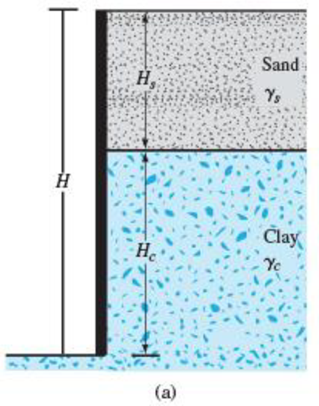
FIG. 15.27 Layered soils in braced cuts
Expert Solution & Answer
Want to see the full answer?
Check out a sample textbook solution
Students have asked these similar questions
(Derive the Rankine active earth pressure of a soil at a depth of z using
Mohr Circles, and failure envelope when the retaining wall has
horizontal ground surface and the unit weight, cohesion, and internal
friction angle of the soils are 7, c, and ø. In addition, what is the
maximum depth of tensile crack at the retaining clay when
Y =15.72kN/m³, cu=6.77kN/m²
9
and ø=30°)
Ir
10000
A cut was made in a homogeneous clay soil to a depth of 8 m as shown in below
Figure. The total unit weight of the soil is 18 kN/m³, and its cohesive strength is 25
kN/m². Assuming a = 0 condition, determine the factor of safety with respect to a
slip circle passing through the toe using Swedish circle method. Consider a tension
crack at the end of the slip circle on the top of the cut.
8 m
R = 12 m
39⁰
6m
Trial
slip circle
y = 18 kN/m³
c'= 25 kN/m²
o'=0
1. Side slopes for rock fill 1V:2H. Calculate the minimum crest width of a breakwater using B = 3*kΔ*(W/γa)1/3 . Given data: Stone weight = (8) t, Specific weight = 2,7 t/m3, Layer thickness coefficient =1,00 and Porosity percentage = 37
2. For cubed shaped stone (or concrete), determine dimension of the stone for weight: W = (10+a) t, specific weight: γa = 2,4 t/m3
Chapter 15 Solutions
Fundamentals of Geotechnical Engineering (MindTap Course List)
Ch. 15 - Prob. 15.1PCh. 15 - Prob. 15.2PCh. 15 - Prob. 15.3PCh. 15 - Prob. 15.4PCh. 15 - Prob. 15.5PCh. 15 - Prob. 15.6PCh. 15 - Prob. 15.7PCh. 15 - Prob. 15.8PCh. 15 - Prob. 15.9PCh. 15 - Prob. 15.10P
Ch. 15 - Prob. 15.11PCh. 15 - Prob. 15.12PCh. 15 - Prob. 15.13PCh. 15 - Prob. 15.14PCh. 15 - Prob. 15.15PCh. 15 - Refer to the braced cut in Figure 15.50, for which...Ch. 15 - For the braced cut described in Problem 15.16,...Ch. 15 - Refer to Figure 15.51 in which = 17.5 kN/m3, c =...Ch. 15 - Refer to Figure 15.27a. For the braced cut, H = 6...Ch. 15 - Prob. 15.20PCh. 15 - Determine the factor of safety against bottom...Ch. 15 - Prob. 15.22PCh. 15 - The water table at a site is at 5 m below the...Ch. 15 - Prob. 15.24PCh. 15 - Prob. 15.25CTPCh. 15 - Figure 15.53 below shows a cantilever sheet pile...
Knowledge Booster


Learn more about
Need a deep-dive on the concept behind this application? Look no further. Learn more about this topic, civil-engineering and related others by exploring similar questions and additional content below.Similar questions
- Refer to Figure, q1 = 90 kN/m; q2 = 325 %3D %3D kN/m; x1 = 4 m; x2 2.5 m; z = 3 m. the vertical stress increase, at point A is nearly (KN/m2) Line load = 91 Line load = 42 Ao 28.6 O 18.6 O 24.6 Oarrow_forwardTwo parallel road tunnels are being constructed for 6 lanes in the basalts. The tun- nels are D-shaped with diameter (B) of around 16 m and 2 m high side walls with clear spacing of 20 m. The maximum overburden (H) is 165 m. The rock mass parameters are, RMR = 73, Q = 10, Ja=1.0, Jr = 3.0 and Jw = 1.0 (minor seepage from side walls). The construction engineers want rapid rate of tunnelling and life of support system should be 100 years. The uniaxial compressive strength of SFRS is 30 MPa and its flexural strength is 3.7 MPa.arrow_forward1. At the bottom of the Lean Clay layer described below, find the total and effective horizontal stresses, Gh, o'h. Make necessary assumption(s) for assigning the ko values. Sand with Silt (SP-SM) 9 m Ve = 19 kN/m³ Lean Clay (CL) PI = 10 Ye = 18.5 kN/m³ o', = 300 kPa m = 0.38 %3D 16 m %3D Dense Silty Sand (SM) Yt = 20.5 kN/m³ Bedrockarrow_forward
- 4.1 There is a strip footing under a masonry wall. Buried depth of footing d=2.4m, width b=3.3m. Subsoil: Ofilling, Y1=18.5kN/m², Y Isat=19.5kN/m², 2m thick; 2clay, e=0.84, L=0.76, Y 2sat=19.8kN/m³, fak=130kPa. Ground water lever is at 1.2m under the ground. Required: Try to modify the bearing capacity according to depth and width of footing.arrow_forwardAn embankment consists of clay fill for which c′ = 25 kN/m2 and φ = 27° (from consolidated undrained tests with pore-pressure measurement). The average bulk unit-weight of the fill is 2 Mg/m3. Estimate the shear-strength in kPa of the material on a horizontal plane at a point 20 m below the surface of the embankment, if the pore pressure at this point is 180 kN/m2 as shown by a piezometer.arrow_forwardProblem # 4. A 2m. clay layer has values of e = 0.92, Gs = 2.72 and liquid limit of 40%. Above the clay is a 3m thick layer of sand with e =0.50 and Gs = 2.62. The water table is located 1.6 m below the ground. If a 3m thick backfill is placed on the ground surface having a unit weight of 17.3 kN/m^3, determine the following: a. Compression index of clay.b. Effective pressure at the midpoint of clay.c. Primary settlement for normally consolidated clay.arrow_forward
- In the excavation of a certain foundation pit, draining water causes upward seepage. The water head difference is 60cm, the length of water flow through the soil is 50cm, the saturated unit weight y=20.5 kN/m². Determine whether the heaving sand happens or not. Give the reason if happens or notarrow_forward3. The coordinates of two points on a given compression curve are as follows: P₁ =200 kPa P2 =400 kPa e₁ = 1.82 e₂ = 1.54 a. Compute the coefficient of compressibility. b. Compute the coefficient of volume compressibility for the pressure stated above. c. Given the coefficient of consolidation C = 0.003 cm²/sec, determine the hydraulic conductivity (k) in cm/sec. corresponding to the average void ratio.arrow_forwardA specimen of saturated sand was consolidated under an all-around pressure of 105kN/m2.The axial stress was then increased and drainage was prevented.The specimen failed when the axial deviator stress reached 70 KN/m2.The pore water pressure at failure was 50 KN/m2.Determine:i. Consolidated-undrained angle of shearing resistance, ɸii. Drained friction angle, ɸ′iii. Sketch Mohr’s circles and Failure Envelops in terms of total and effective stress.iv. Assuming soil specimen to be homogenous, sketch a network of failure planes.arrow_forward
- Given: 1. Structural Component: Beam 300 mm x 400 mm Column 400 mm x 400 mm Slab thickness 110 mm 2. Dead Load: Super Imposed dead load = 4.5 KPa (including slab weight) CHB = 3.11 KPa 3. Seismic Parameter: Soil Profile - Sb Closest distance to the source - 10 km Ductility Coefficient R = 8.0 Seismic Zone Z=0.40 Ct = 0.0731 A. Compute TOTAL LATERAL FORCES in the 2nd floor? B. Compute LATERAL FORCES in the 3rd floor?arrow_forwardY=15kN/m²³ Y=12.5 kN/m³ 0 p = 150 kPa e₁ = 0.95 KON.C.=0.57 m = 0.4 Y = 27.5 kN/m³ sand 9m Clay [ Bedrock * ↑ 3m ↓ 18m 5m ↓↓↓ A) What is the total vertical stress, o (in kPa) at the mid point of the clay layer? B) What is the pore water pressure, u linkPa) at the midpoint of the clay layer? c) What is the effective vertical Stress, o'v (in kPa) at the midpoint of the clay layer D) What is the over consolidated Ratio (OCR) at the midpoint of the clay layer? E) What is the total horizontal Stress (inkPa) at the midpoint of the clay layer?arrow_forwardA retaining wall is shown below to support two layers of soil. fc' = 23 MPa and fy = 420 MPa. Use 28mm diameter bars for the transverse reinforcement and 12mm for the longitudinal reinforcement. The parameters per layer are given below: Surcharge = qs = 8.04 kPa. Layer 1: H1 = 1.96m. γ = 15.74 kN/m3. Φ = 21 degrees Layer 2: H2 = 4.98m. Gs = 2.64. e = 0.44. S = 23.32%. Φ = 31 degrees. What is the minimum wall thickness (mm)?arrow_forward
arrow_back_ios
SEE MORE QUESTIONS
arrow_forward_ios
Recommended textbooks for you
 Fundamentals of Geotechnical Engineering (MindTap...Civil EngineeringISBN:9781305635180Author:Braja M. Das, Nagaratnam SivakuganPublisher:Cengage Learning
 Principles of Foundation Engineering (MindTap Cou...Civil EngineeringISBN:9781305081550Author:Braja M. DasPublisher:Cengage Learning
Fundamentals of Geotechnical Engineering (MindTap...
Civil Engineering
ISBN:9781305635180
Author:Braja M. Das, Nagaratnam Sivakugan
Publisher:Cengage Learning
Principles of Foundation Engineering (MindTap Cou...
Civil Engineering
ISBN:9781305081550
Author:Braja M. Das
Publisher:Cengage Learning
How to build angle braces; Author: Country Living With The Harnish's;https://www.youtube.com/watch?v=3cKselS6rxY;License: Standard Youtube License