
Fundamentals of Geotechnical Engineering (MindTap Course List)
5th Edition
ISBN: 9781305635180
Author: Braja M. Das, Nagaratnam Sivakugan
Publisher: Cengage Learning
expand_more
expand_more
format_list_bulleted
Concept explainers
Videos
Textbook Question
Chapter 15, Problem 15.17P
For the braced cut described in Problem 15.16, assume that σall = 170 MN/m2.
- a. Determine the sheet pile section (section modulus)
- b. What is the section modulus of the wales at level A?
15.16 Refer to the braced cut in Figure 15.50, for which γ = 17 kN/m3, ϕ′ = 30°, and c′ = 0. The struts are located at 3 m on center in the plan. Draw the earth pressure envelope and determine the strut loads at levels A, B, and C.
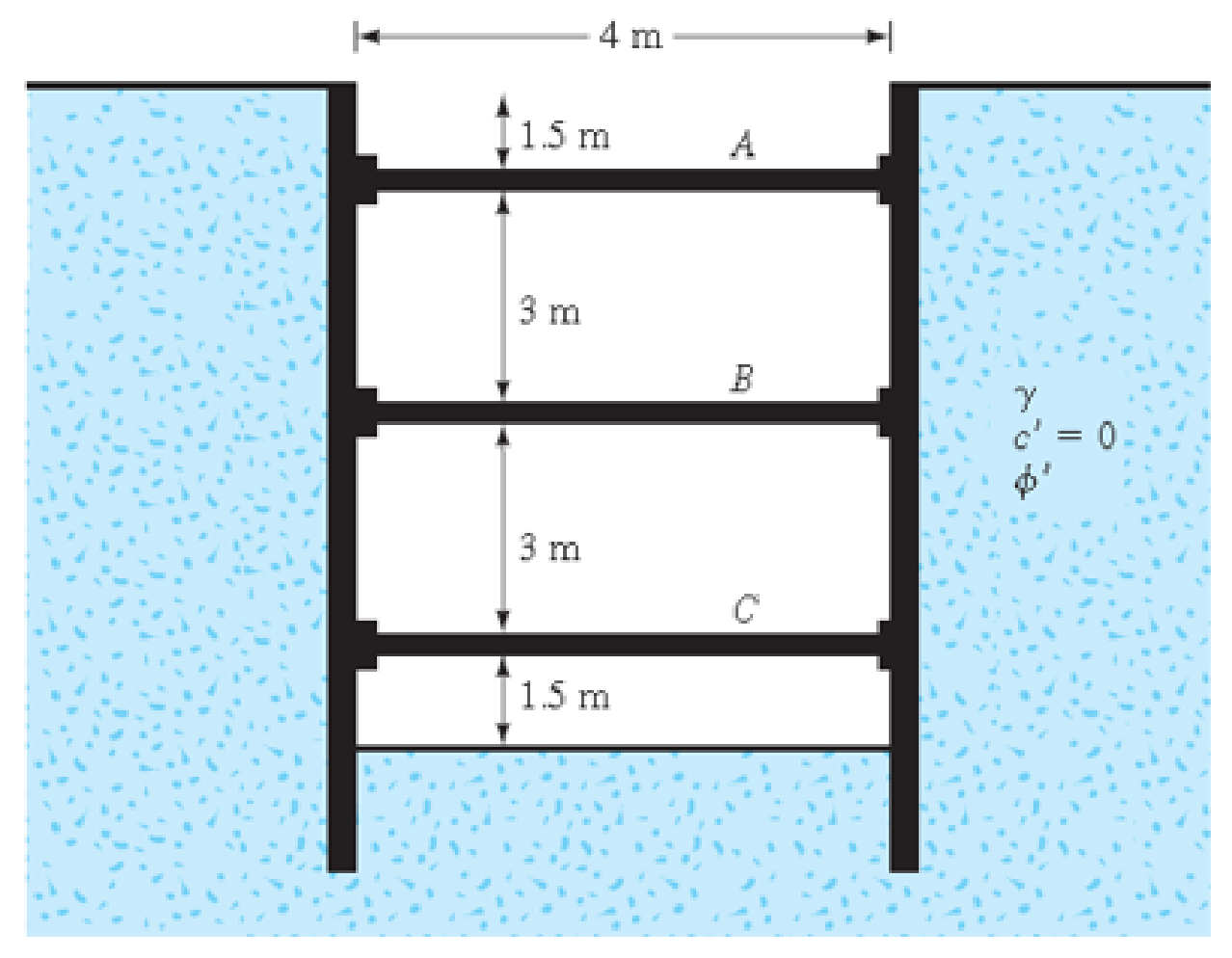
FIG. 15.50
Expert Solution & Answer

Trending nowThis is a popular solution!

Students have asked these similar questions
Question 2
Refer to the braced cut shown in Figure Q2, for which y = 17.6 kN/m², 6' = 32°, and c’ = 0.
The struts are located 4 m on center-to-center in the plan. Draw the earth-pressure envelope and
determine the strut loads at levels A, B, and C.
Determine also:
a. The sheet-pile section modulus, assume that Gan =170 x 10³ kN/m?
b. The required section modulus of the wales at level A; assume that Gan = 173 x 10º kN/m²
-5 m-
2 m
A
3 m
В
c = 0
3 m
C
1 m
Refer to the braced cut shown below. Given: unit weight = 17 kN/m3, Friction angle = 35degrees, and c = 0. The struts are located at 3 m center-to-center in the plan. a. Draw the earth-pressure envelope and determine the strut loads at levels A, B, and C. b. Determine the sheet-pile section modulus c. Determine the section modulus of the wales at level B Assume that = 170 MN/m2.
Problem #2
Refer to the braced cut shown below. Given: unit weight = 17 kN/m³,
Friction angle = 35degrees, and c = 0. The struts are located at 3 m center-to-center in
the plan.
a. Draw the earth-pressure envelope and determine the strut loads at levels A, B, and
C.
b. Determine the sheet-pile section modulus
c. Determine the section modulus of the wales at level B
Assume that all = 170 MN/m².
-3.5 m
1m
2m
2 m
1.5 m
A
B
Sand
y = 17 kN/m³
$'= 35°
c'=0
Chapter 15 Solutions
Fundamentals of Geotechnical Engineering (MindTap Course List)
Ch. 15 - Prob. 15.1PCh. 15 - Prob. 15.2PCh. 15 - Prob. 15.3PCh. 15 - Prob. 15.4PCh. 15 - Prob. 15.5PCh. 15 - Prob. 15.6PCh. 15 - Prob. 15.7PCh. 15 - Prob. 15.8PCh. 15 - Prob. 15.9PCh. 15 - Prob. 15.10P
Ch. 15 - Prob. 15.11PCh. 15 - Prob. 15.12PCh. 15 - Prob. 15.13PCh. 15 - Prob. 15.14PCh. 15 - Prob. 15.15PCh. 15 - Refer to the braced cut in Figure 15.50, for which...Ch. 15 - For the braced cut described in Problem 15.16,...Ch. 15 - Refer to Figure 15.51 in which = 17.5 kN/m3, c =...Ch. 15 - Refer to Figure 15.27a. For the braced cut, H = 6...Ch. 15 - Prob. 15.20PCh. 15 - Determine the factor of safety against bottom...Ch. 15 - Prob. 15.22PCh. 15 - The water table at a site is at 5 m below the...Ch. 15 - Prob. 15.24PCh. 15 - Prob. 15.25CTPCh. 15 - Figure 15.53 below shows a cantilever sheet pile...
Knowledge Booster


Learn more about
Need a deep-dive on the concept behind this application? Look no further. Learn more about this topic, civil-engineering and related others by exploring similar questions and additional content below.Similar questions
- The cross section of a braced cut supporting a sheet pile installation in a clay soil is shown in Figure 14.22. Given: H = 12 m, clay = 17.9 kN/m3, = 0, c = 75 kN/m2, and the center-to-center spacing of struts in plan view, s = 3 m. a. Using Pecks empirical pressure diagrams, draw the earth-pressure envelope. b. Determine the strut loads at levels A, B, and C.arrow_forwardThe cross section of a braced cut supporting a sheet pile installation in a clay soil is shown in the figure below. Given: H = 12 m , clay = 17.9 kN/m3 , = 0 , C = 75 kN/m2 , and the center-to-center spacing of struts in plan view , S = 3 m.arrow_forwardThe braced cut of two layers of clay is shown in the figure. 1.0000 H; = 3 m; Y = 16 kN/m³ c; = 21 kN/m² H = 3 m; Y2= 17 kN/m² ez= 22 kN/m² H3 = 2 m; y3 = 18 kN/m³ c3= 23 kN/m? 3.0000 2.0000 Clay 1 B The struts are located 4 m on center in the plan. 2.0000 3.0000 Determine the strut load at D. Clay 2- 2.0000 D 1.0000 Clay 3 A 427.32 kN 424.32 kN 437.32 kN D 227.32 kN to B.arrow_forward
- Given: γ =17.5 kN/m3c = 30 kN/m2center-to-center spacing of struts in the plan = 5 m. Determine the sheet-pile section modulus for the braced cut. Use σ all = 170 MN/m2arrow_forwardDetermine the factor of safety against bottom heave for the braced cut described in Problem 15.18. Use Eqs. (15.66) and (15.70). For Eq. (15.70), assume the length of the cut, L = 18 m. 15.18 Refer to Figure 15.51 in which = 17.5 kN/m3, c = 60 kN/m2, and center-to-center spacing of struts is 5 m. Draw the earth pressure envelope and determine the strut loads at levels A, B, and C. FIG. 15.51arrow_forward(a) A retaining wall with a sandy soil as backfill is shown as in FIGURE Q4(a). It is very important that the retaining wall is design accordingly to avoid failure. (i) Design the size of the retaining wall. (ii) Since the consultant want to use pile as a foundation, proposed the others stability of the retaining wall. 0.1 H Soil properties for backfill y = 18 kN/m³ p' = 32° 6.0 m 0.1 H 0.15 H Soil properties below the cantilever wall Y = 17.1 kN/m³ p' = 28° 0.7 H FIGURE Q4 (a) : Retaining wallarrow_forward
- An excavation in soft clay is supported by a braced sheet pile wall. Calculate the force in strut A. O a. 631.92 kN O b. 151.67 kN O c. 203.53 kN O d. 430.87 kN Struts are spaced 2.5 m centre to centre Soft clay %=17kN/m³ S20 kPa $=0° max=yH = YH (1-4) H Q|25Harrow_forwardThe braced cut of two layers of clay is shown in the figure. 1.0000 A H; = 3 m; Y1 = 16 kN/m² c; = 21 kN/m² H; = 3 m; Y2= 17 kN/m³ cz= 22 kN/m² H3 = 2 m; Y3 = 18 kN/m² c3 = 23 kN/m² 3.0000 2.0000 Clay 1 The struts are located 4 m on center in the plan. 2.0000 Determine the strut load at C. 3.0000 - Clay 2 2.0000 1.0000 Clay 3. A 332.63 kN В 333.36 kN 332.36 kN D 322.36 kNarrow_forward2. Assuming a sheet pile wall is constructed to retain 12.5m of soil, as shown in Figure 2, and the water is 2m above the bottom of wall, compute the resultant lateral force acting on the upper12.5m of the sheet- pile wall. Assume a surcharge load of 6.7kN/m2 and consider tension cracks in your calculation. 5m Sandy clay c=25KN/m², =10°, y=18KN/m³ 7.5m Silt c=10KN/m², 0=15°, y=20KN/m³ Sand =35°, y=19KN/m³ Figure 2arrow_forward
- A 5 m wide braced excavation is made in a saturated clay, as shown in Figure P19.1, with the following properties: c =20 kN/m?, 4= 0, and y = 18.5 kN/m³. The struts are spaced at 5 m center to center in plan. a. Determine the strut forces. b. Determine the section modulus of the sheet pile required, assuming oall = 170 MN/m². c. Determine the maximum moment for the wales at levels B and C. 5 m A 1 m | 3 m B | 2 m Imarrow_forwardThe braced cut of two layers of clay is shown in the figure. 1.0000 H; = 3 m; Y = 16 kN/m² c; = 21 kN/m² H2 = 3 m; Y2 = 17 kN/m³ cz = 22 kN/m² H3 = 2 m; y3= 18 kN/m³ ¢3 = 23 kN/m² 3.0000 2.0000 Clay 1 B The struts are located 4 m on center in the plan. 2.0000 Determine the strut load at B. 3.0000 - Clay 2– 2.0000 D 1.0000 Clay 3 A 344 kN B 664 kN 564 kN D 364 kNarrow_forwardA concrete retaining wall 8 m high is supporting a horizontal backfill having a dry unit weight of 16.25kN/m3. The cohesionless soil has an angle of internal friction of 33 degrees and a void ratio 0f 0.65. (Use four decimal places) A. Compute the rankine active force on the wall. B. Compute the rankine active force on the wall if water logging occurs at a depth of 3.5 from the ground surface. C. Compute the location of the resultant active force from the bottom.arrow_forward
arrow_back_ios
SEE MORE QUESTIONS
arrow_forward_ios
Recommended textbooks for you
 Fundamentals of Geotechnical Engineering (MindTap...Civil EngineeringISBN:9781305635180Author:Braja M. Das, Nagaratnam SivakuganPublisher:Cengage Learning
 Principles of Foundation Engineering (MindTap Cou...Civil EngineeringISBN:9781305081550Author:Braja M. DasPublisher:Cengage Learning
 Principles of Geotechnical Engineering (MindTap C...Civil EngineeringISBN:9781305970939Author:Braja M. Das, Khaled SobhanPublisher:Cengage Learning
 Principles of Foundation Engineering (MindTap Cou...Civil EngineeringISBN:9781337705028Author:Braja M. Das, Nagaratnam SivakuganPublisher:Cengage Learning
Fundamentals of Geotechnical Engineering (MindTap...
Civil Engineering
ISBN:9781305635180
Author:Braja M. Das, Nagaratnam Sivakugan
Publisher:Cengage Learning
Principles of Foundation Engineering (MindTap Cou...
Civil Engineering
ISBN:9781305081550
Author:Braja M. Das
Publisher:Cengage Learning
Principles of Geotechnical Engineering (MindTap C...
Civil Engineering
ISBN:9781305970939
Author:Braja M. Das, Khaled Sobhan
Publisher:Cengage Learning
Principles of Foundation Engineering (MindTap Cou...
Civil Engineering
ISBN:9781337705028
Author:Braja M. Das, Nagaratnam Sivakugan
Publisher:Cengage Learning
How to build angle braces; Author: Country Living With The Harnish's;https://www.youtube.com/watch?v=3cKselS6rxY;License: Standard Youtube License