
Principles of Geotechnical Engineering (MindTap Course List)
9th Edition
ISBN: 9781305970939
Author: Braja M. Das, Khaled Sobhan
Publisher: Cengage Learning
expand_more
expand_more
format_list_bulleted
Concept explainers
Videos
Textbook Question
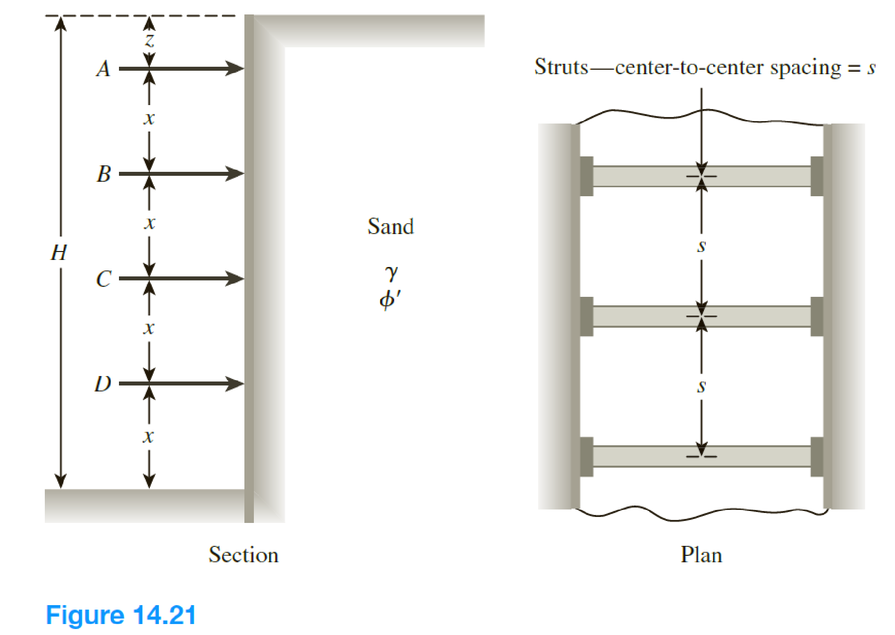
Chapter 14, Problem 14.14P
The elevation and plan of a bracing system for an open cut in sand are shown in Figure 14.21. Using Peck’s empirical pressure diagrams, determine the design strut loads. Given: γsand = 18 kN/m3, ϕ' = 38°, x = 3 m, z = 1.25 m, and s = 3 m.
Expert Solution & Answer

Trending nowThis is a popular solution!

Students have asked these similar questions
Situation 1| An overhang beam is loaded as shown below. The beam cross-section
was built by attaching two (2) channels to a 9mm thick plate using 16mm rivets.
The property of the channel is given below:
Depth, D = 225 mm
Flange Thickness, t; = 9mm
Flange Width, B, =112.5 mm
Web Thickness, t, =9 mm
The allowable flexural stress on the beam is 180 MPa. Rivets has a capacity of t=
100 MPa on shear, for bearing, o,=200 MPa on single shear, o, =260MPA on double
shear.
a. Determine the maximum shearing stress on the beam
in MPa
b. Determine the flexural stress, in MPa, on the fiber
above 30mm above N.A at distance 1m from A.
c.Determine the shearing stress, in MPa, on the fiber
above 30mm above N.A at distance 1m from A.
225
P= 8
P= 10
9,- 18
H3
2 (m)
1 (m) .
4.50 (m)
1.50 (m)
Situation 1| An overhang beam is loaded as shown below. The beam cross-section
was built by attaching two (2) channels to a 9mm thick plate using 16mm rivets.
The property of the channel is given below:
Depth, D = 225 mm
Flange Thickness, t, = 9mm
Flange Width, B; =112.5 mm
Web Thickness, tw=9 mm
The allowable flexural stress on the beam is 180 MPa. Rivets has a capacity of t=
100 MPa on shear, for bearing, o,=200 MPa on single shear, o,-260MPA on double
shear.
1. Determine the location of centroid, y, from top of the beam in mm.
2. Determine the moment of inertia, I, of the section in mm“.
3. Determine the maximum allowable moment, Mall, in kn-m, base on the
beam's cross-section.
Chapter 14 Solutions
Principles of Geotechnical Engineering (MindTap Course List)
Knowledge Booster


Learn more about
Need a deep-dive on the concept behind this application? Look no further. Learn more about this topic, civil-engineering and related others by exploring similar questions and additional content below.Similar questions
- Determine the factor of safety against bottom heave for the braced cut described in Problem 15.18. Use Eqs. (15.66) and (15.70). For Eq. (15.70), assume the length of the cut, L = 18 m. 15.18 Refer to Figure 15.51 in which = 17.5 kN/m3, c = 60 kN/m2, and center-to-center spacing of struts is 5 m. Draw the earth pressure envelope and determine the strut loads at levels A, B, and C. FIG. 15.51arrow_forwardGiven : A rectangular post-tensioned prestressed beam has a width of 300mm, total depth of 600 mm, and a simply supported span of 12m. Grade 1860 stress relieved prestressing tendons are used with variable eccentricity. The total area of the tendons, subjected to an effective prestressing force of 637.5 KN, is equal to 650.3 sq.mm. Calculate and Draw the Tendon Profile. Use Eps = 186 MPa, fc’ = 35MPa, fci’ = 26MPa. R = 0.85 Assume that the maximum moment due to the uniformly distributed sustained service loads, including self weight, is 202.5 KN-m.arrow_forwardA short rectangular post supports a compressive load of P = 210 kN as shown. A top view of the post showing the location where load P is applied to the top of the post is also shown. Determine the vertical normal stress at corner d of the post. -9.14 MPa -15.12 MPa -11.20 MPa -12.06 MPa -14.02 MPaarrow_forward
- Example 7: Determine the factor of safety of the bottom against heave for the very long braces system shown below. Make reasonable assumptions if necessary. 10 kN/m? B= 5m Ø =33° Y = 18 kN/m H=4m Sand 3 3 qu = 80 kN/m² Y= 19 kN/m³ H=4m Clayarrow_forwardSituation 9: An 8m deep braced cuts in medium clay is shown. The unit weight = 16.5 kN/m3 and the undrained shear strength Cu = 27.8 kPa. In the plan, the struts are placed at spacing 2.4m center to center. Using Peck's Empirical pressure diagram: m 0.25H 2m В H= 8 m 0.75 H 2|m 2|m Pa = yh - 4Cu %3D 41. Compute the actual load on strut A. A. 124.57 kN C. 116.47 kN B. 153.48 kN D. 162.81 kN 42. Compute the actual load on strut B. А. 33.29 kN C. 28.42 kN B. 40.54 kN D. 35.29 kN 43. Compute the actual load on strut C. A. 127.92 kN C. 131.95 kN B. 210.38 kN D. 199.68 kNarrow_forward1. Determine the force F per metre width (into the page) of the rectangular prismatic concrete block shown on the figure below, that would lead to sliding of the block. The water depth is 10m and the unit weight of concrete is 24 kN/m³. 10m 5m 2.5m Sand sea bed, d=p²=35°arrow_forward
- A braced cut shown in Figure P19.3 is to be made to a depth of 9.0 m in a saturated clay deposit where the unit weight is 17.65 kN/m3 and the undrained shear strength is 30 kN/m2. The struts are spaced horizontally at 3.0 m center to center. Find the strut loads.arrow_forwardThe cross section of a braced cut supporting a sheet pile installation in a clay soil is shown in Figure 14.22. Given: H = 12 m, clay = 17.9 kN/m3, = 0, c = 75 kN/m2, and the center-to-center spacing of struts in plan view, s = 3 m. a. Using Pecks empirical pressure diagrams, draw the earth-pressure envelope. b. Determine the strut loads at levels A, B, and C.arrow_forwardCan someone please solve this? Find load function functions and draw load effect diagrams? Fx=4.5KN.Fz=2.5 KNMB = 2.5 KNm.a= 1.6M.arrow_forward
- Refer to the braced cut shown in the figure for which y= 20 kN/m², o'=23°, and c' = 0. 2.0000 The struts are located 5 m on center in the plan. Determine the strut load at A. 3.0000 3.0000 2.0000 A 1186.45 kN В 237.29 474.26 D 1816.29arrow_forwardA roadway sign weighs 7.2 kN and is supported by a structural pipe that has an outside diameter of 250 mm and a wall thickness of 11 mm. The resultant force of the wind pressure acting on the sign is 9 kN, as shown. Assume a = 8.2 m, b = 3 m, Pz = 9 kN, and %3D Py = 7.2 kN. (a) Determine the normal and shear stresses oH, TxyH at point H. (b) Determine the normal and shear stresses OK, TyzK at point K. a H K Answers: OH = i MPа. TxyH 28.6 MPa. OK i MPа. TyzK i ! MPa. IIarrow_forwardA cantilever beam supports the loads shown. The cross-sectional dimensions of the shape are also shown. Assume a = 0.6 m, PA = 2.5 kN, PB = 7.0 kN, PC = 4.0 kN, d = 100 mm, bf = 110 mm, tf = 10 mm, tw = 7 mm. Determine(a) the maximum vertical shear stress.(b) the maximum compression bending stress.(c) the maximum tension bending stress. See the coordinate system for the beam in the problem figure with the origin of the x axis at the fixed support. Consider four points along the beam’s axis:Point A at x = 1.8 mPoint B at x = 1.2 mPoint C at x = 0.6 mPoint D at x = 0Break the beam into three segments: AB, BC, and CD. Enter the shear force in each segment with its correct sign based on the coordinate system in the problem figure and the sign convention for shear forces in Chapter 7.Answers: VAB = kN VBC = kN VCD = kN Enter the maximum shear force magnitude in the beam. Since this is a magnitude, enter a positive value.Answer: Vmax = kN Enter the…arrow_forward
arrow_back_ios
SEE MORE QUESTIONS
arrow_forward_ios
Recommended textbooks for you
 Principles of Geotechnical Engineering (MindTap C...Civil EngineeringISBN:9781305970939Author:Braja M. Das, Khaled SobhanPublisher:Cengage Learning
 Fundamentals of Geotechnical Engineering (MindTap...Civil EngineeringISBN:9781305635180Author:Braja M. Das, Nagaratnam SivakuganPublisher:Cengage Learning
 Principles of Foundation Engineering (MindTap Cou...Civil EngineeringISBN:9781305081550Author:Braja M. DasPublisher:Cengage Learning
 Principles of Foundation Engineering (MindTap Cou...Civil EngineeringISBN:9781337705028Author:Braja M. Das, Nagaratnam SivakuganPublisher:Cengage Learning
Principles of Geotechnical Engineering (MindTap C...
Civil Engineering
ISBN:9781305970939
Author:Braja M. Das, Khaled Sobhan
Publisher:Cengage Learning
Fundamentals of Geotechnical Engineering (MindTap...
Civil Engineering
ISBN:9781305635180
Author:Braja M. Das, Nagaratnam Sivakugan
Publisher:Cengage Learning
Principles of Foundation Engineering (MindTap Cou...
Civil Engineering
ISBN:9781305081550
Author:Braja M. Das
Publisher:Cengage Learning
Principles of Foundation Engineering (MindTap Cou...
Civil Engineering
ISBN:9781337705028
Author:Braja M. Das, Nagaratnam Sivakugan
Publisher:Cengage Learning
How to build angle braces; Author: Country Living With The Harnish's;https://www.youtube.com/watch?v=3cKselS6rxY;License: Standard Youtube License