
Principles of Geotechnical Engineering (MindTap Course List)
9th Edition
ISBN: 9781305970939
Author: Braja M. Das, Khaled Sobhan
Publisher: Cengage Learning
expand_more
expand_more
format_list_bulleted
Concept explainers
Videos
Textbook Question
Chapter 14, Problem 14.15P
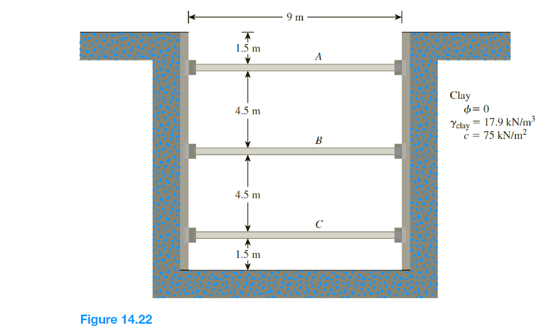
The cross section of a braced cut supporting a sheet pile installation in a clay soil is shown in Figure 14.22. Given: H = 12 m, γclay = 17.9 kN/m3, ϕ = 0, c = 75 kN/m2, and the center-to-center spacing of struts in plan view, s = 3 m.
- a. Using Peck’s empirical pressure diagrams, draw the earth-pressure envelope.
- b. Determine the strut loads at levels A, B, and C.
Expert Solution & Answer

Trending nowThis is a popular solution!

Students have asked these similar questions
The cross section of a braced cut supporting a sheet pile installation in a clay soil is shown in the figure
below. Given: H = 12 m , clay = 17.9 kN/m3
, = 0 , C = 75 kN/m2
, and the center-to-center spacing of
struts in plan view , S = 3 m.
The T section is shown in Figure below is the cross-section of a beam. The beam is subjected
to a uniform distributed load = 4 kN/m. The N.A is located at 34.7 mm from the bottom and
that IxA =10.64x106 mm. Determine (a) the maximum shearing suess (b) the shearing stress at
15 mm from the bottom face.
Q2
%3D
20mm
4 kN/m
120mm
A
34.7 mm
20mm
lm
3m
1m
220mm
TT
1. Determine the force F per metre width (into the page) of the rectangular prismatic
concrete block shown on the figure below, that would lead to sliding of the block. The
water depth is 10m and the unit weight of concrete is 24 kN/m³.
10m
5m
2.5m
Sand sea bed, d=p²=35°
Chapter 14 Solutions
Principles of Geotechnical Engineering (MindTap Course List)
Knowledge Booster


Learn more about
Need a deep-dive on the concept behind this application? Look no further. Learn more about this topic, civil-engineering and related others by exploring similar questions and additional content below.Similar questions
- For the beam shown, determine the support reactions and draw the stress diagrams.shear and bending moment. EI is constant. Use the force method. I have a correct answer, it is: VA = 44.3 kN (↑); HA = 0 kN; MA = 34.3 kN.m (counterclockwise); VB = 38 kN (↑). I don't know how to get to this result, please show me how to get there step by steparrow_forwardQ3) A retaining structure is given in figure. Calculate the factor of safety against sliding. (Ignore tensile crack behavior inside active part and ground water condition. Take 1.0 m interval step for point load calculation. k₁= k₂= 0.9). 3.B m 2.C m Yn: 20.0 kN/m² D: 2Eº c: 30 kN/m² 0.5 m 0.5 m 1 3.0 m 5.0 m Y cone ➜ 5A0 KN Yn: 18.5 kN/m³ c: 18 kN/m² $: ID º 24.0 kN/m³arrow_forwardRefer to the braced cut shown in the figure for which y= 20 kN/m², o'=23°, and c' = 0. 2.0000 The struts are located 5 m on center in the plan. Determine the strut load at A. 3.0000 3.0000 2.0000 A 1186.45 kN В 237.29 474.26 D 1816.29arrow_forward
- H.W: For the following Gravity Dam, Yw=10 KN/m³, Y.-24 KN/m³,q= 1400 KN/m² and μ= 0.7. a. Calculate the uplift force acting on the base of the dam. b. Check whether the section is safe against sliding. c. Check whether the section is safe against overturning. d. Determine the maximum vertical stress at the toe of the dam. e. Determine the maximum vertical stress at the heel Determine the Principal stress at the toe of the dam. g. Determine the Principal stress at the heel of the dam h. Determine the shear stress at the heel of the dam. i. Determine the shear stress at the Toe of the dam. зт 6m T 10m 27m 0175 20marrow_forward• A two-span continuous one-way slab with span length of 4.3 meters is integral with its beam supports which are 300 mm wide with spacing 2m on center. The slab carries a factored load of 27000 Pa. f'c = 21Mpa and fy = 275 Mpa. a. Determine the minimum depth of slab (mm). b. Compute the positive and negative factored bending moments (KN-m). c. Calculate the spacing of 10mm main bars (mm). d. Find the spacing of 10mm temperature bars (mm).arrow_forwardConstruct the shear-force diagram and identify the largest negative shear force. Assume a = 5.8 ft, b = 11.6 ft, c = 23.2 ft, w = 1060 Ib/ft, and P = 2800 Ib. A C D a barrow_forward
- A long braced cut shown is supporting a layer of clay. Angle of fraction is 0. The struts are placed 3m center to center. a.) Determine the reaction of the strut at B. b.) Determine the section modulus of wale at B if the allowable bending stress is 0.6Fy where Fy = 250Mpaarrow_forwardGiven : A rectangular post-tensioned prestressed beam has a width of 300mm, total depth of 600 mm, and a simply supported span of 12m. Grade 1860 stress relieved prestressing tendons are used with variable eccentricity. The total area of the tendons, subjected to an effective prestressing force of 637.5 KN, is equal to 650.3 sq.mm. Calculate and Draw the Tendon Profile. Use Eps = 186 MPa, fc’ = 35MPa, fci’ = 26MPa. R = 0.85 Assume that the maximum moment due to the uniformly distributed sustained service loads, including self weight, is 202.5 KN-m.arrow_forwardA post having a hollow, circular cross section supports a P = 3.5 kN load acting at the end of an arm that is b = 1.5 m long (see figure). 1.5 m, B 9 m C (-3.2 m, 2.5 m, 0) The height of the post is L = 9 m, and its section modulus is S = 2.56 x 10° mm³. Assume that the outer radius of the post isr, = 121 mm, and the inner radius is r, = 115 mm. (Assume that the structure behaves linearly elastically and that the stresses caused by two or more loads may be superimposed to obtain the resultant stresses acting at a point. Consider both in-plane and out-of-plane shear stresses unless otherwise specified.) (a) Calculate the maximum tensile stress omay and maximum in-plane shear stress tmay at point A on the outer surface of the post along the x-axis due to the load P. Load P acts at B along line BC. (Enter the magnitudes in MPa.) MPа = 'max MPa Tmaxarrow_forward
- A concrete, gravity dam has the following cross section properties as given in the figure below. The uplift pressure at the base of the dam varies linearly from 60% hydrostatic pressure at heel to zero at toe. Specific gravity of concrete is 2.4 a. Calculate the factor of safety against sliding. Use u = 0.6. b. Calculate the factor of safety against overturning. c. Solve for the location of the resultant force from the toe d. Calculate the maximum soil pressure developed at the base of the dam. e. Calculate the minimum soil pressure developed at the base of the dam. 2.6 m 8. 21.6 m 18.6 m 12 marrow_forwardH.W: For the following Gravity Dam, Y=10 KN/m³, y=24 KN/m³,q= 1400 KN/m² and μ= 0.7. a. Calculate the uplift force acting on the base of the dam. b. Check whether the section is safe against sliding. c. Check whether the section is safe against overturning. d. Determine the maximum vertical stress at the toe of the dam. e. Determine the maximum vertical stress at the heel f. Determine the Principal stress at the toe of the dam. g. Determine the Principal stress at the heel of the dam h. Determine the shear stress at the heel of the dam. Determine the shear stress at the Toe of the dam. i. эт 6m T 27m 0.75 10m 20marrow_forwardDetermine the factor of safety against bottom heave for the braced cut described in Problem 15.18. Use Eqs. (15.66) and (15.70). For Eq. (15.70), assume the length of the cut, L = 18 m. 15.18 Refer to Figure 15.51 in which = 17.5 kN/m3, c = 60 kN/m2, and center-to-center spacing of struts is 5 m. Draw the earth pressure envelope and determine the strut loads at levels A, B, and C. FIG. 15.51arrow_forward
arrow_back_ios
SEE MORE QUESTIONS
arrow_forward_ios
Recommended textbooks for you
 Principles of Geotechnical Engineering (MindTap C...Civil EngineeringISBN:9781305970939Author:Braja M. Das, Khaled SobhanPublisher:Cengage Learning
 Fundamentals of Geotechnical Engineering (MindTap...Civil EngineeringISBN:9781305635180Author:Braja M. Das, Nagaratnam SivakuganPublisher:Cengage Learning
 Principles of Foundation Engineering (MindTap Cou...Civil EngineeringISBN:9781305081550Author:Braja M. DasPublisher:Cengage Learning
Principles of Geotechnical Engineering (MindTap C...
Civil Engineering
ISBN:9781305970939
Author:Braja M. Das, Khaled Sobhan
Publisher:Cengage Learning
Fundamentals of Geotechnical Engineering (MindTap...
Civil Engineering
ISBN:9781305635180
Author:Braja M. Das, Nagaratnam Sivakugan
Publisher:Cengage Learning
Principles of Foundation Engineering (MindTap Cou...
Civil Engineering
ISBN:9781305081550
Author:Braja M. Das
Publisher:Cengage Learning
How to build angle braces; Author: Country Living With The Harnish's;https://www.youtube.com/watch?v=3cKselS6rxY;License: Standard Youtube License