Concept explainers
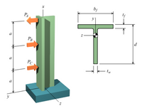
A cantilever beam supports the loads shown. The cross-sectional dimensions of the shape are also shown. Assume a = 0.6 m, PA = 2.5 kN, PB = 7.0 kN, PC = 4.0 kN, d = 100 mm, bf = 110 mm, tf = 10 mm, tw = 7 mm. Determine
(a) the maximum vertical shear stress.
(b) the maximum compression bending stress.
(c) the maximum tension bending stress.
See the coordinate system for the beam in the problem figure with the origin of the x axis at the fixed support. Consider four points along the beam’s axis:
Point A at x = 1.8 m
Point B at x = 1.2 m
Point C at x = 0.6 m
Point D at x = 0
Break the beam into three segments: AB, BC, and CD. Enter the shear force in each segment with its correct sign based on the coordinate system in the problem figure and the sign convention for shear forces in Chapter 7.
Answers:
| VAB = | kN |
| VBC = | kN |
| VCD = | kN |
Enter the maximum shear force magnitude in the beam. Since this is a magnitude, enter a positive value.
Answer: Vmax = kN
Enter the bending moment at four critical x-locations:
MD is the moment at x = 0
MC is the moment at x = 0.6 m
MB is the moment at x = 1.2 m
MA is the moment at x = 1.8 m
Enter each bending moment with its correct sign based on the coordinate system in the problem figure and the sign convention for bending moments presented in Chapter 7.
Answers:
| MA = | kN-m |
| MB = | kN-m |
| MC = | kN-m |
| MD = | kN-m |
Answers:
| Mmax, + = | kN-m |
| Mmax, - = | kN-m |
Break the cross-sectional area into two areas:
(1) Top horizontal flange with rectangular cross-section 110 mm × 10 mm.
(2) Vertical stem with rectangular cross-section 7 mm × 90 mm.
Find the areas and the centroid locations in the y-direction for each area. Enter the centroid locations, y1 and y2, as measured with respect to a reference axis at the bottom of the cross-section. In other words, let y = 0 at the bottom edge of the vertical stem.
Answers:
| A1 = | mm2, | y1 = | mm |
| A2 = | mm2, | y2 = | mm |
Answer: y¯ = mm
(1) Top horizontal flange with rectangular cross-section 110 mm × 10 mm.
(1) Top horizontal flange with rectangular cross-section 7 mm × 90 mm.
Determine the moment of inertia for each area about its own centroid and the distance from the centroid of each area to the centroid of the entire cross-section. For example, Ic1 is the moment of inertia for area (1) about its own centroid, and d1 is the distance from the centroid of area (1) to the centroid of the entire cross-section calculated in Step 6. Enter the distances d1 and d2 as positive values here, regardless of whether the centroid for an area is above or below the centroid of the entire cross-section.
Answers:
| Ic1 = | (103) mm4, | d1 = | mm |
| Ic2 = | (103) mm4, | d2 = | mm |
Answer: Iz = (106) mm4
Answer: Qmax = (103) mm3
Answer: τmax= MPa
Answers:
| σT+= | MPa |
| σC+ | MPa |
Answers:
| σT-= | MPa |
| σT-= | MPa |
Answer: σC,max= MPa
Answer: σT,max= MPa

Trending nowThis is a popular solution!
Step by stepSolved in 3 steps with 3 images

- The circular shaft shown is subjected to an axial force P at its free end and a compressive force of 50 kips at point B. Note that the shaft is hollow between points A and B. The allowable normal tension stress is 22 ksi, the modulus of elasticity is 29,000 ksi, and the maximum allowable elongation is 0.04 in. Determine the maximum allowable value of P in kips. -0.75 in A B C 50 kips 3 in 20 in 30 inarrow_forwardplease answer, with written solution thanksarrow_forward

 Structural Analysis (10th Edition)Civil EngineeringISBN:9780134610672Author:Russell C. HibbelerPublisher:PEARSON
 Principles of Foundation Engineering (MindTap Cou...Civil EngineeringISBN:9781337705028Author:Braja M. Das, Nagaratnam SivakuganPublisher:Cengage Learning
 Fundamentals of Structural AnalysisCivil EngineeringISBN:9780073398006Author:Kenneth M. Leet Emeritus, Chia-Ming Uang, Joel LanningPublisher:McGraw-Hill Education
 Traffic and Highway EngineeringCivil EngineeringISBN:9781305156241Author:Garber, Nicholas J.Publisher:Cengage Learning


