
Concept explainers
Videos
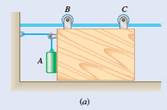
(a)
The acceleration of the panel and the tension in the cord after the system released from rest.
Answer to Problem 12.29P
Acceleration of the panel
Tension in the cord
Explanation of Solution
Given information:
Weight of panel
Weight of the counterweight
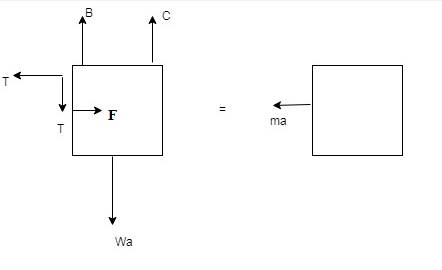
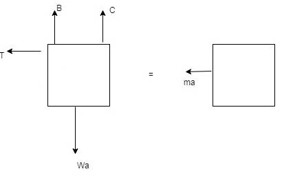
First, we draw the free body diagram and kinetic diagram of the panel:
F = force exerted by counterweight
Weight
Now, force
Now, computing the forces for counterweight A,
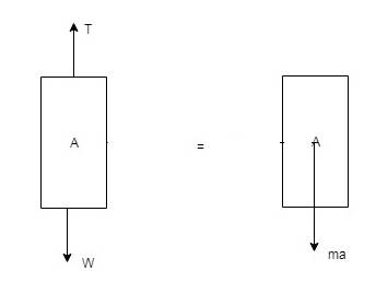
For this we draw the free body and kinetic diagram of the counterweight A;
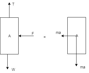
Hence, from the above diagram it is clear that the acceleration component of counterweight A has two components.
Now,
Now, adding equation (1), (2) and (3);
Now, Tension in the cord from equation (3),
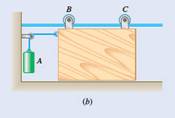
(b)
The acceleration of the panel and the tension in the cord after the system released from rest.
Answer to Problem 12.29P
Acceleration of the panel
Tension in the cord
Explanation of Solution
Given information:
Weight of panel
Weight of the counterweight
First, we draw the free body diagram and kinetic diagram of the panel:
F = force exerted by counterweight.
Weight
Now, force
Now, computing the forces for counterweight A,
For this we draw the free body and kinetic diagram of the counterweight A;
Now, adding equation (1) and (2);
Now, Tension in the cord from equation (1),
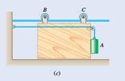
(c)
The acceleration of the panel and the tension in the cord after the system released from rest.
Answer to Problem 12.29P
Acceleration of the panel
Tension in the cord
Explanation of Solution
Given information:
Weight of panel
Weight of the counterweight
First, we draw the free body diagram and kinetic diagram of the panel:
F = force exerted by counterweight
Weight
Now, force
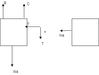
Since, panel is accelerated to the left, there is no force exerted by the panel on counterweight hence;
Now, computing the forces for counterweight A,
For this, we draw the free body and kinetic diagram of the counterweight A;

Now, adding equation (1) and (2);
Now, Tension in the cord from equation (1),
Want to see more full solutions like this?
Chapter 12 Solutions
Vector Mechanics For Engineers


- A garage door is mounted on an overhead rail. The wheels at A and B have rusted so that they do not roll, but rather slide along the track. The coefficient of kinetic friction is 0.55. The distance between the wheels is 2.00 m, and each is 0.50m from the vertical sides of the door. The door is uniform and weighs 850 N. It is pushed to the left at constant speed by a horizontal force F⃗, that is applied as shown in the figure. If the distance h is 1.60 m, what is the vertical component of the force exerted on the wheel A by the track? If the distance h is 1.60 m, what is the vertical component of the force exerted on the wheel B by the track? Find the maximum value hh can have without causing one wheel to leave the track.arrow_forwardSample Problem 16.3 150 mm 30 B F 200 mm 30% D 500 mm The thin plate of mass 8 kg is held in place as shown. Neglecting the mass of the links, determine immediately after the wire has been cut (a) the acceleration of the plate, and (b) the force in each link.arrow_forwardA 60-lb uniform thin panel is placed in a truck with end A resting on a rough horizontal surface and end B supported by a smooth vertical surface. Knowing that the panel remains in the position shown, determine (a) the maximum allowable acceleration of the truck, (b) the corresponding minimum required coefficient of static friction at end A.arrow_forward
- 2. The figure shows a system in a vertical plane. A block with mass m is in rest on top of the frictionless horizontal surface of the prism with mass M, at the most right-hand side of the surface. That prism itself is in rest on a frictionless inclined plane. The length of the side of the prism on which the block rests is d. a) What are the accelerations of the block m and of the prism M immediately after they are released from rest? What is at that instance the relative acceleration of the block m with respect to the prism M? b) How long does it take for the block to find itself at the other side of the horizontal surface of the prism, hence, at the most left-hand side of the horizontal surface? What are at that instance the velocities of block and prism? Data: m = 0.7 kg; M = 5 kg; d = 0.8 m 30° d 3 3 M 30%arrow_forwardEnd A of the 8-kg uniform rod AB is attached to a collar that can slide without friction on a vertical rod. End B of the rod is attached to a ver- tical cable BC. If the rod is released from rest in the position shown, determine immediately after release (a) the angular acceleration of the rod, (b) the reaction at A. Please show clear diagrams.arrow_forwardProblem #5) A pulley having a moment of inertia of 0.191b-ft-s² is connected to two masses as shown. The masses A and B have linear acceleration of 1.85ft/s² upward and 1.11 ft/s² downward, respectively. Assuming no axle friction, determine (a) the tension forces TA and TB in the cables connecting the masses, and (b) the angular acceleration a of the pulley. 6 in. Include and present the Free Body Diagram and Inertial Response Diagram as part of the solving process. Hint #1: Hint #2: use mA = 0.1553slugs, and mB = 0.3106slugs treat each body separately B 10 lb 10 in. A 5 lbarrow_forward
- Required information NOTE: This is a multi-part question. Once an answer is submitted, you will be unable to return to this part. A 3.5-kg slender rod AB and a 2-kg slender rod BC are connected by a pin at B and by the cord AC. The assembly can rotate in a vertical plane under the combined effect of gravity and a couple M applied to rod BC. In the position shown, the angular velocity of the assembly is zero and the tension in cord AC is equal to 26.8 N. 300 mm A 400 mm 400 mm M B Determine the angular acceleration of the assembly. (You must provide an answer before moving to the next part.) rad/s²0. The angular acceleration of the assembly isarrow_forwarda. Each arm of a Porter governor is 200 mm long and is hinged at a distance of 40 mm from the axis of rotation. The mass of each ball is 1.5 kg and of the sleeve 25 kg. When the links are at 30° to the vertical, the sleeve begins to rise at 260 rpm. Assuming that the friction force is constant, find the maximum and minimum speeds of rotation when the inclination of the arms to the vertical is 45°. b. The four arms of a porter governor is 250 mm long. The upper and lower arms are pivoted to links 40 mm and 50 mm respectively from the axis of rotation. Each ball has a mass of 5 kg and the sleeve mass is 50 kg. The force of friction on the sleeve of the mechanism is 40 N. Determine the range of speed of the governor for extreme radii of rotation of 125 mm and 150 mm. Consider the force diagrams attached.arrow_forwardThe uniform rod AB of weight W is released from rest when β = 70°. Assuming that the friction force between end A and the surface is large enough to prevent sliding, determine immediately after release (a) the angular acceleration of the rod, (b) the normal reaction at A, (c) the friction force at A.arrow_forward
- B. L 15° 30° A uniform bar of mass 166.93 kg and length L=2.1 m is supported by two massless frictionless roller blocks in the vertical plane, and held in static equilibrium by a horizontal force P at point A as shown. If the acceleration due to gravity g=9.81 m/s², determine the magnitude of P. O a. P = 409.51 N O b. P = 409.40 N O c. P = 409.30 N O d. P = 409.64 N e. P = 409.77 N O f. P = 409.21 Narrow_forwardA uniform rod AB, of mass 15 kg and length 1 m, is attached to the 20-kg cart C. Neglecting friction, determine immediately after the system has been released from rest, (a) the acceleration of the cart, (b) the angular acceleration of the rod.arrow_forwardb. The four arms of a porter governor is 250 mm long. The upper and lower arms are pivoted to links 40 mm and 50 mm respectively from the axis of rotation. Each ball has a mass of 5 kg and the sleeve mass is 50 kg. The force of friction on the sleeve of the mechanism is 40 N. Determine the range of speed of the governor for extreme radii of rotation of 125 mm and 150 mm. Consider the force diagrams attached.arrow_forward
 Elements Of ElectromagneticsMechanical EngineeringISBN:9780190698614Author:Sadiku, Matthew N. O.Publisher:Oxford University Press
 Mechanics of Materials (10th Edition)Mechanical EngineeringISBN:9780134319650Author:Russell C. HibbelerPublisher:PEARSON
 Thermodynamics: An Engineering ApproachMechanical EngineeringISBN:9781259822674Author:Yunus A. Cengel Dr., Michael A. BolesPublisher:McGraw-Hill Education
 Control Systems EngineeringMechanical EngineeringISBN:9781118170519Author:Norman S. NisePublisher:WILEY
 Mechanics of Materials (MindTap Course List)Mechanical EngineeringISBN:9781337093347Author:Barry J. Goodno, James M. GerePublisher:Cengage Learning
 Engineering Mechanics: StaticsMechanical EngineeringISBN:9781118807330Author:James L. Meriam, L. G. Kraige, J. N. BoltonPublisher:WILEY