Concept explainers
The geometry of a centrifugal water pump is r1 = 10 cm, r2 = 20 cm, b1 = b2 = 4 cm, β1 = 30°, β2 = 15°, and it runs at speed 1600 rpm. Estimate the discharge required for axial entry, the power generated in the water in watts, and the head produced.
The discharge required for axial entry, the power generated in the water in watts, and the head produced.
Explanation of Solution
Given:
Inlet impeller radius is
Outlet impeller radius is
Inlet blade angle is
Outlet blade angle is
Speed of the centrifugal water pump is
Inlet tangential velocity is
Impeller inlet width
Impeller outlet width
Calculation:
Calculate the angular speed of centrifugal water pump
Calculate the runner speed at inlet
Calculate the runner speed at outlet
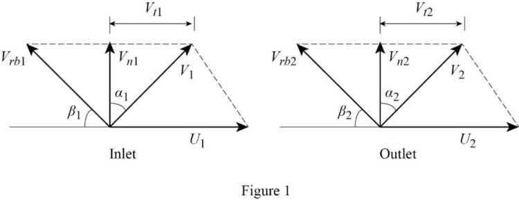
Draw inlet and outlet velocity diagram as shown in Figure (1).

From Figure (1).
At inlet,
Calculate
Using continuity equation calculate the discharge required at the entry
Thus, the discharge required at the entry
At Outlet,
Calculate tangential velocity at outlet
Calculate the theoretical power generated in the water
Thus, the power generated in the water
Calculate the theoretical head
Thus, the theoretical head
Want to see more full solutions like this?
Chapter 10 Solutions
Fox and McDonald's Introduction to Fluid Mechanics
Additional Engineering Textbook Solutions
Thinking Like an Engineer: An Active Learning Approach (4th Edition)
Engineering Mechanics: Dynamics (14th Edition)
Engineering Mechanics: Statics & Dynamics (14th Edition)
Thinking Like an Engineer: An Active Learning Approach (3rd Edition)
Manufacturing Engineering & Technology
Degarmo's Materials And Processes In Manufacturing
- 3. A centrifugal pump has d1 = 7 in., d2 = 13 in., b1 = 4 in., b2 = 3 in., 1 = 25, 2 = 40 and rotates at 1160 rev/min. If the fluid is gasoline at 20C and the flow enters the blades radially, Estimate the theoretical (a) flow rate, in gpm; (b) the water horsepower; and (c) the head in ft. b. flow rate Answer : _______________ gpmc. water horsepower Answer : _______________ HPd. head Answer : _______________ ftarrow_forwardProblem 1(5): A centrifugal pump transports water between two reservoirs. The pump has an outer diameter of 15 cm, an inner diameter of 8 cm, and a blade width of 2 cm and operates at 1750 rpm. If the water enters the pump axially at ẞ₁ = 45º¸ compute the volume flow rate, Problem 2(10): In the pump of problem 1, the water exits at B₂ 65° when the pump is driven at 1750 rpm. = Compute the minimum power required by the pump?arrow_forward- A centrifugal pump with an impeller diameter of 350mm and specific speed of 19.15 and requires 15 kW to discharge 2.4 m³ /min of water, and runs at 1800 rpm. Determine the discharge, head and power required when the pump runs at 2400 rpm. The same discharge could be obtained by altering the impeller diameter without changing the rotational speed for this case find the new diameter of the impeller the head and the power required.arrow_forward
- The fluid flow rate was 1 m3 / s and the head was 10 m in the experiment performed at 2000 rpm with the 1/4 ratio model of a centrifugal pump designed to be used for oil. Calculate the power given by the pump to the fluid when the prototype pump operates at 1000 rpm. (ρsu = 1000 kg / m3, ρ oil = 800 kg / m3)arrow_forwardA centrifugal pump has d1=1.5 cm ,d2=3 cm, b1= 1cm, b2= 0.7 cm, B1= 25° , and B=40° and rotates at 1200 r/min . If the fluid is blood and the flow enters the blades radially, estimate the theoretical (a) flow rate in l/min ,(b) power and (c) , head , known the blood density is 1070 kg/m3arrow_forwardA centrifugal pump impeller has an external diameter of 1.2 m and internal diameter of 0.8 m. The width of the impeller at outlet is 0.175 m and the blade angle at outlet is 65 degrees. The flow velocities at inlet and outlet are the same (Va1 = Va2). This pump delivers 1.55 m3/s of water at 210 rpm. For theoretical performance, calculate: 1-The flow velocity . 2-blade speed at outlet. 3-blade angle at inlet (in degrees). 4-the developed head. 5-The pressure rise across the impeller. 6-The number of blades . 7-The NPSH . %3Darrow_forward
- For a centrifugal pump of impeller diameter D rotating at N to develop a head of H and discharge Q, what would be the new head developed by the same pump if we halve the impeller speed to N/2? H/A 2H H 4H H/2arrow_forward6. A centrifugal pump is directly coupled to a motor. The pump rating is 3,281 liters per minute against a total head of 8 meters. Pump efficiency is 65% at shaft speed of 770 rpm. Shaft diameter is 40 mm. Calculate the (a) torque delivered by the shaft in N-m and (b) the torsional stress induced on the motor shaft in kPa.arrow_forwardA centrifugal pump delivers 2.5 cfs of water against a head of 25 ft at 1500 rpm and requires 10 hp. If the speed is reduced to 1250 rpm calculate the flow (in m^3/s), assuming the same efficiency.arrow_forward
- A centrifugal pump is generating a flow rate of 16 m3/min and a lift of 70 m at a rotational speed of 1560 rpm. What is the maximum allowable suction height for this pump? However, the water temperature is 40°C.arrow_forwardQuestion 2 A centrifugal pump delivers 0.1 m³/s of water at a rotational speed of 1200 rev/min. The impeller has seven vanes which lean backwards to the direction of rotation such that the blade tip angle is 40°. The impeller has an external diameter of 0.4 m, an internal diameter of 0.2m and an axial width of 31.7 mm. Assuming that the diffuser efficiency is 51.5%, that the impeller head losses are 10% of the ideal head rise and that the diffuser exit is 0.15m in diameter, determine (a) The manometric head (b) The hydraulic efficiencyarrow_forwardA centrifugal pump equipped with a variable frequency (speed) drive running at 3300 rpm is discharging 250 gallons per minute corresponding with a head of 235 feet. The horsepower is 34.2. If the pump’s speed is reduced to 2700 rpm, what will be the revised flow rate, head, and power required?arrow_forward
 Elements Of ElectromagneticsMechanical EngineeringISBN:9780190698614Author:Sadiku, Matthew N. O.Publisher:Oxford University Press
 Mechanics of Materials (10th Edition)Mechanical EngineeringISBN:9780134319650Author:Russell C. HibbelerPublisher:PEARSON
 Thermodynamics: An Engineering ApproachMechanical EngineeringISBN:9781259822674Author:Yunus A. Cengel Dr., Michael A. BolesPublisher:McGraw-Hill Education
 Control Systems EngineeringMechanical EngineeringISBN:9781118170519Author:Norman S. NisePublisher:WILEY
 Mechanics of Materials (MindTap Course List)Mechanical EngineeringISBN:9781337093347Author:Barry J. Goodno, James M. GerePublisher:Cengage Learning
 Engineering Mechanics: StaticsMechanical EngineeringISBN:9781118807330Author:James L. Meriam, L. G. Kraige, J. N. BoltonPublisher:WILEY


