
Concept explainers
Videos
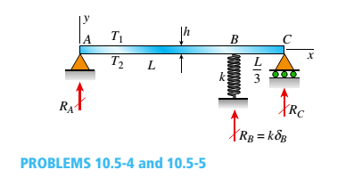
Solve the preceding problem by integrating the differential equation of the deflection curve.
(a)
The reactions for beam at all supports.
Answer to Problem 10.5.5P
The reaction at support
The reaction at support
The reaction at support
Explanation of Solution
Given information:
The two spans of beam are
Write the Expression for force equilibrium in vertical direction.
Here, reaction produced at
Write the expression for moment about point
Here,
Write the expression for moment about point
Here,
Write the expression for double order differential equation for the deflection curve when any value between
Here, double order differential of deflection curve is
Write the expression for single order derivative of deflection curve when any value between
Here, length at which deflection has to be calculate is
Write the expression for deflection curve when any value between
Here, deflection at a point
Write the expression for first boundary condition.
Here, deflection when
Write the expression for second boundary condition when
Here, single order differential of deflection curve from the loads left to spring is
Write the expression for third boundary condition when
Write the expression for fourth boundary condition.
Here, deflection when
Write the expression for differential equation for the deflection curve when any value between
Write the expression for single order derivative of deflection curve when any value between
Write the expression for deflection curve when any value between
Write the expression for compatibility Equation for spring when
Substituted
Substitute
Substitute
Substitute
Substitute
Substitute
Substitute
Substitute
Substitute
Substitute
Substitute
Substitute
Substitute
Solve Equation (XXIII) and Equation (XXIV).
Substitute
Conclusion:
The reaction at support
The reaction at support
The reaction at support
(b)
The reactions at all the supports when value of
Answer to Problem 10.5.5P
The reaction at support
The reaction at support
The reaction at support
Explanation of Solution
Take limit of
Take limit of
Take limit of
Conclusion:
The reaction at support
The reaction ay support
The reaction at support
Want to see more full solutions like this?
Chapter 10 Solutions
Mechanics of Materials (MindTap Course List)


- A cantilever beam of a length L and loaded by a uniform load of intensity q has a fixed support at A and spring support at B with rotational stiffness kR. A rotation B at B results in a reaction moment MB=kRxB. Find rotation B and displacement Bat end B. Use the second-order differential equation of the deflection curve to solve for displacements at end B.arrow_forwardSolve the preceding problem for a W 250 × 89 steel column having a length L = 10 m. Let E = 200 GPa.arrow_forwardSolve the preceding problem for a box beam with dimensions h = 0.5 m, h = 0.18 m, and t = 22 mm. The yield stress of the steel is 210 MPa.arrow_forward
- -4 A beam with a uniform load has a sliding support at one end and spring support at the other. The spring has a stiffness k = 48IE/ L2. Derive the equation of the deflection curve by starting with the third-order differential equation (the shear-force equation). Also, determine the angle of rotation Bat support B.arrow_forwardA cable CD of a length H is attached to the third point of a simple beam AB of a length L (see figure). The moment of inertia of the beam is I, and the effective cross-sectional area of the cable is A. The cable is initially taut but without any initial tension, (a) Obtain a formula for the tensile force S in the cable when the temperature drops uniformly by T degrees, assuming that the beam and cable are made of the same material (modulus of elasticity E and coefficient of thermal expansion . Use the method of superposition in the solution, (b) Repeat part (a), assuming a wood beam and steel cable.arrow_forwardAssume that the deflected shape of a beam AB with immovable pinned supports (see figure) is given by the equation v = - sinx/L, where is the deflection at the midpoint of the beam and L is the length. Also, assume that the beam has constant axial rigidity EA. Obtain formulas for the longitudinal force H at the ends of the beam and the corresponding axial tensile stress t. For an aluminum-alloy beam with E = 10 × 106 psi, calculate the tensile stress twhen the ratio of the deflection S to the length L equals 1/200, 1/400, and 1/600.arrow_forward
- -14 A cantilever beam AB supporting a triangularly distributed load of maximum intensity q0is shown in the figure. Derive the equation of the deflection curve and then obtain formulas for the deflection Band angle of rotation Bat the free end. Use the second-order differential equation of the deflection curve.arrow_forwardA beam ABC with simple supports at A and B and an overhang BC supports a concentrated load P at the free end C (see figure). Determine the strain energy Ustored in the beam due to the load P. From the strain energy, find the deflection Scunder the load P. Calculate the numerical values of £/and Sc if the length L is 8 ft, the overhang length a is 3 ft, the beam is a W 10 x 12 steel wide-flange section, and the load P produces a maximum stress of 12,000 psi in the beam, (Use £ = 29 X 106 psi.)arrow_forwardBeam ABC is loaded by a uniform load q and point load P at joint C. Using the method of superposition, calculate the deflection at joint C. Assume that L = 4 m, a =2ra, q = 15 kN/m, P = 7.5 kN, £ = 200 GPa, and / = 70.8 X 106 mm4.arrow_forward
- Compound beam ABC is loaded by point load P = 1.5 kips at distance 2aB from point A and a triangularly distributed load on segment BC with peak intensity qü= 0.5 kips/ft. If length a = 5 ft and length/) = 10 ft, find the deflection at B and rotation at A. Assume that £ = 29,000 ksi and / = 53.8 in4.arrow_forwardA heavy object of weight W is dropped onto the midpoint of a simple beam AB from a height h (see figure). Obtain a formula for the maximum bending stress ^ma* due to tne filing weight in terms of h, st, and 5st, where it is the maximum bending stress and Sstis the deflection at the midpoint when the weight W acts on the beam as a statically applied load. Plot a graph of the ratio o"max/ö"it (that is, the ratio of the dynamic stress to the static stress) versus the ratio iifS^r(Let h/S^ vary from 0 to 10.)arrow_forward-20 Derive the equations of the deflection curve for a cantilever beam AB carrying a uniform load of intensity q over part of the span (see figure). Also, determine the deflection Bat the end of the beam. Use the second-order differential equation of the deflection curve.arrow_forward
 Mechanics of Materials (MindTap Course List)Mechanical EngineeringISBN:9781337093347Author:Barry J. Goodno, James M. GerePublisher:Cengage Learning